6 F 3 H 1 0 0 1
9.3 Saving Waveforms
NOTES
When the unit has stopped due to failure, be sure to remove the memory card before resetting the LCD Failure Error screen on the panel, so you can give it to the service person.
Resetting (restarting) the UPS without removing the memory card will delete the data needed to determine the cause of the failure.
Every effort has been made to ensure safety in unit handling. However, when removing the memory card, do not touch the other sections of the unit.
Touching the other sections of the unit may result in electric shock.
When a trip error occurs, do the following:
[Procedure]
Trip error occurs; UPS stops operating
↓
(1)Open the front door on the UPS graphic display panel (see Figure 5.1 on page 11).
↓
(2)Remove the memory card from the back of the door.
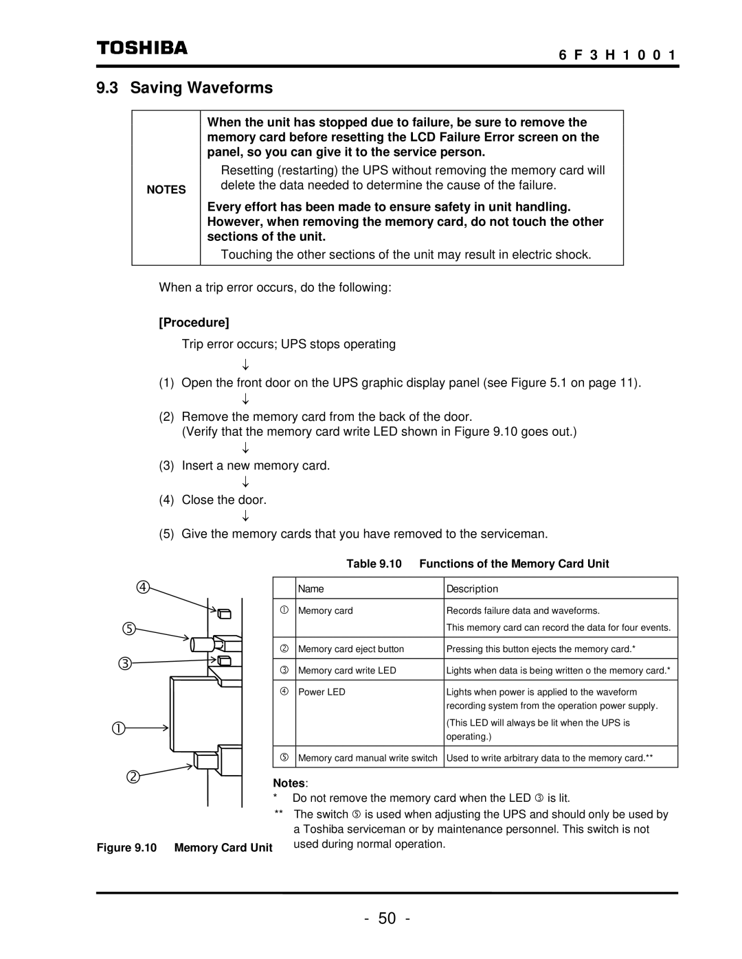
(Verify that the memory card write LED shown in Figure 9.10 goes out.)
↓
(3)Insert a new memory card.
↓
(4)Close the door.
↓
(5)Give the memory cards that you have removed to the serviceman.
f
g![]() e
e![]()
c![]()
d![]()
Figure 9.10 Memory Card Unit
| Table 9.10 | Functions of the Memory Card Unit | |
|
|
|
|
| Name |
| Description |
|
|
|
|
c | Memory card |
| Records failure data and waveforms. |
|
|
| This memory card can record the data for four events. |
|
|
|
|
d | Memory card eject button |
| Pressing this button ejects the memory card.* |
|
|
|
|
e | Memory card write LED |
| Lights when data is being written o the memory card.* |
|
|
|
|
f | Power LED |
| Lights when power is applied to the waveform |
|
|
| recording system from the operation power supply. |
|
|
| (This LED will always be lit when the UPS is |
|
|
| operating.) |
|
|
| |
g | Memory card manual write switch | Used to write arbitrary data to the memory card.** | |
|
|
|
|
Notes:
*Do not remove the memory card when the LED e is lit.
**The switch g is used when adjusting the UPS and should only be used by a Toshiba serviceman or by maintenance personnel. This switch is not used during normal operation.
- 50 -
