6 F 3 H 1 0 0 1
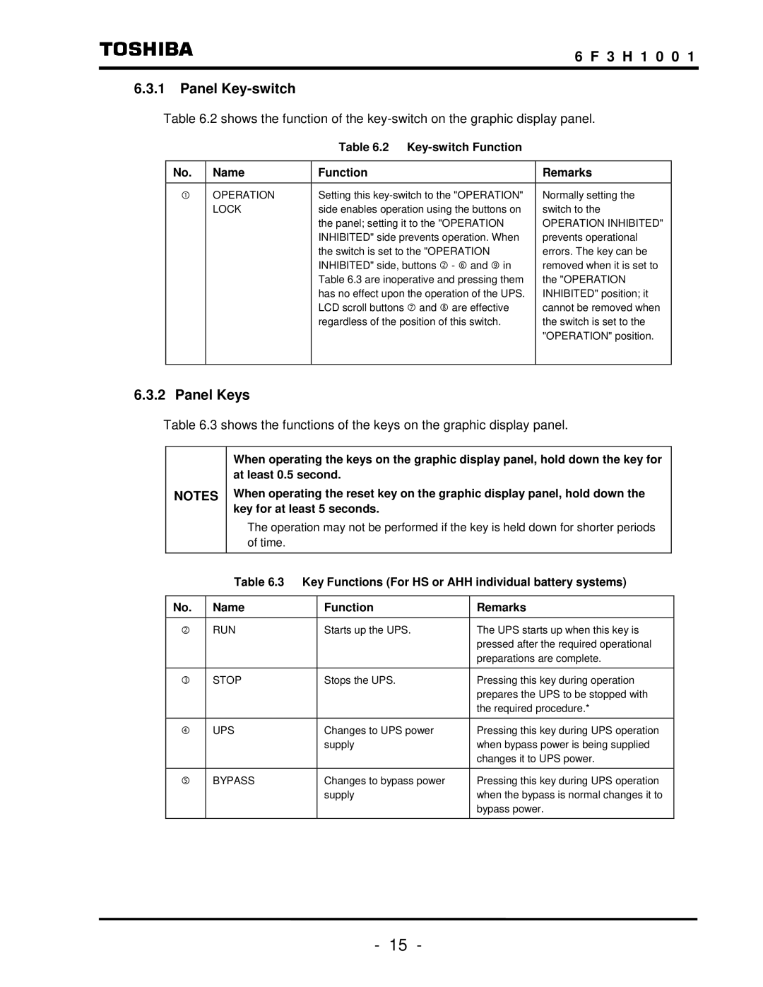
6.3.1Panel Key-switch
Table 6.2 shows the function of the
Table 6.2 Key-switch Function
No. | Name | Function | Remarks |
|
|
|
|
c | OPERATION | Setting this | Normally setting the |
| LOCK | side enables operation using the buttons on | switch to the |
|
| the panel; setting it to the "OPERATION | OPERATION INHIBITED" |
|
| INHIBITED" side prevents operation. When | prevents operational |
|
| the switch is set to the "OPERATION | errors. The key can be |
|
| INHIBITED" side, buttons d - h and k in | removed when it is set to |
|
| Table 6.3 are inoperative and pressing them | the "OPERATION |
|
| has no effect upon the operation of the UPS. | INHIBITED" position; it |
|
| LCD scroll buttons i and j are effective | cannot be removed when |
|
| regardless of the position of this switch. | the switch is set to the |
|
|
| "OPERATION" position. |
|
|
|
|
6.3.2 Panel Keys
Table 6.3 shows the functions of the keys on the graphic display panel.
NOTES
When operating the keys on the graphic display panel, hold down the key for at least 0.5 second.
When operating the reset key on the graphic display panel, hold down the key for at least 5 seconds.
The operation may not be performed if the key is held down for shorter periods of time.
Table 6.3 Key Functions (For HS or AHH individual battery systems)
No. | Name | Function | Remarks |
|
|
|
|
d | RUN | Starts up the UPS. | The UPS starts up when this key is |
|
|
| pressed after the required operational |
|
|
| preparations are complete. |
|
|
|
|
e | STOP | Stops the UPS. | Pressing this key during operation |
|
|
| prepares the UPS to be stopped with |
|
|
| the required procedure.* |
|
|
|
|
f | UPS | Changes to UPS power | Pressing this key during UPS operation |
|
| supply | when bypass power is being supplied |
|
|
| changes it to UPS power. |
|
|
|
|
g | BYPASS | Changes to bypass power | Pressing this key during UPS operation |
|
| supply | when the bypass is normal changes it to |
|
|
| bypass power. |
|
|
|
|
- 15 -