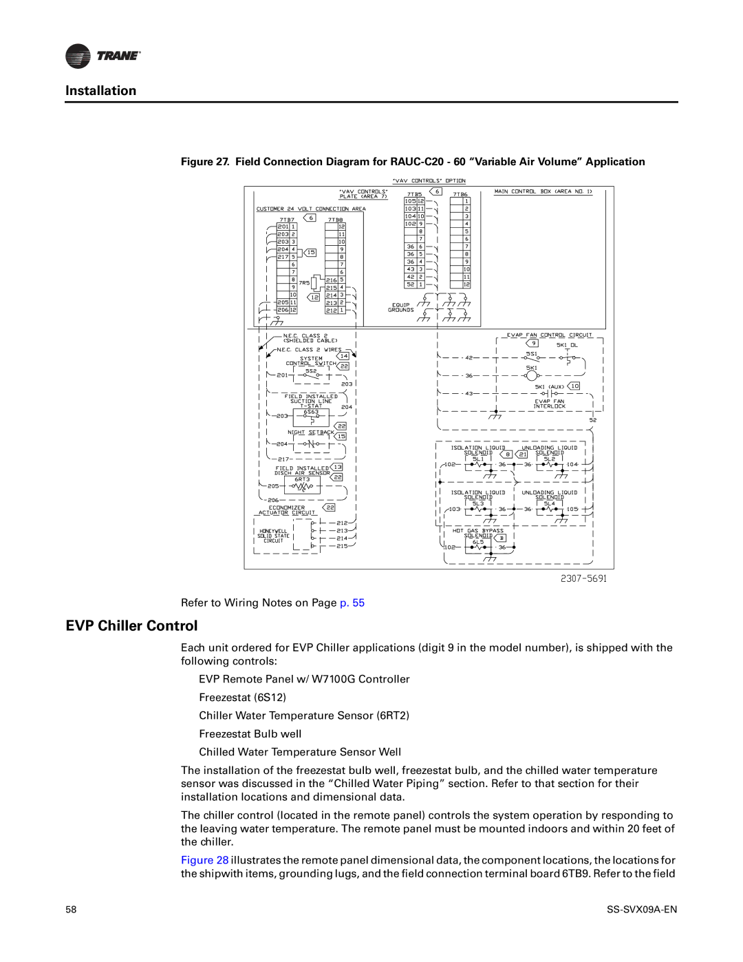
RAUC-C20, RAUC-C40, RAUC-C25, RAUC-C30, RAUC-C60 specifications
Trane, a leader in HVAC solutions, offers innovative air conditioning units designed for superior performance and energy efficiency. Among their advanced products are the Trane RAUC-C30, RAUC-C20, RAUC-C40, RAUC-C60, and RAUC-C50, which cater to various cooling and heating needs in residential and commercial applications.The RAUC-C series showcases cutting-edge technology, ensuring effective climate control while minimizing energy consumption. These units are equipped with variable-speed compressors, allowing for precise cooling capacities and reduced noise levels during operation. This feature ensures that users can enjoy optimal comfort without the disruptive noise often associated with traditional HVAC systems.
One of the standout technologies used in the RAUC-C series is Trane’s advanced inverter technology. This system intelligently adjusts the compressor speed based on real-time cooling demands, enhancing efficiency and prolonging the unit's lifespan. Additionally, the units come with high SEER (Seasonal Energy Efficiency Ratio) ratings, making them an excellent choice for those looking to lower their energy bills while maintaining a comfortable indoor environment.
The RAUC-C series units are designed with durability in mind. Constructed with robust materials, these air conditioning systems are built to withstand varying weather conditions. Their compact and lightweight design makes installation straightforward, and they can fit seamlessly into a variety of spaces, from residential homes to commercial buildings.
Another key characteristic of the RAUC-C series is their eco-friendly refrigerant, which meets strict environmental regulations. This not only supports sustainability efforts but also ensures efficient cooling performance. Furthermore, their smart technology capabilities enable integration with modern smart home systems, allowing users to manage their cooling settings remotely for added convenience.
Trane's focus on user-friendly interfaces makes these units easy to operate. The intuitive control systems allow users to customize their cooling preferences easily, providing flexibility to adapt to individual comfort needs.
Overall, the Trane RAUC-C30, RAUC-C20, RAUC-C40, RAUC-C60, and RAUC-C50 stand out for their energy efficiency, advanced technology, durability, and user-focused design. These features make them reliable choices for anyone seeking efficient and effective heating and cooling solutions.

