Not suitable for mobile applications
Input/Output 220/380V, 230/400V or 240/415V AC, 3O, 4-wire + ground
Models SU20KX, SU40KX, SU60KX, SU80KX
Owner’s Manual
1 Table of Contents
1 - Introduction
Advanced Features
Connection Warnings
1 2 - Important Safety Instructions
SAVE THESE INSTRUCTIONS
Location Warnings
Battery Warnings
2 - Important Safety Instructions
Wiring Warnings
1 3 - Control Panel Features
D Output Circuit Breaker Switch Q4 Controls AC output power
4 - Front and Rear Panel Features
SU40KX shown front
Levelers The levelers provide long-term support for the UPS system
Read Section 2 - Important Safety Instructions Before Installation
5 - Cabinet Installation
5-1 Preparation
5-2 Unpacking
is moved over an unstable surface. Be extremely careful when
1 5 - Cabinet Installation continued
5-3 Placement
the shipping container. Warning The UPS system could tip if it
SU40KX shown
6-1 Internal Battery Wiring Diagrams
DANGER! LETHAL HIGH VOLTAGE HAZARD
SU40KX shown
Connector
1 6 - Internal Battery Connection continued
6-1 Internal Battery Wiring Diagrams continued
Battery Back
6-2 Internal Battery Connection Procedure
6 - Internal Battery Connection continued
potential arcing of connectors. Blown fuses must be replaced
1 6 - Internal Battery Connection continued
6-2 Internal Battery Connection Procedure continued
Warning Battery cartridge fuses must be inserted last due to
6-2 Internal Battery Connection Procedure continued
6 - Internal Battery Connection continued
13 Replace the battery access bezels
DANGER! LETHAL HIGH VOLTAGE HAZARD
1 7 - Wiring
7-1 Wiring Warnings
7-2 Wiring Preparation
External Battery Cabinet Breaker Switch
7 - Wiring continued
7-3 UPS System Terminal Block Diagram
7-4 External Battery Cabinet Wiring Diagrams
External Battery Cabinets
1 7 - Wiring continued
7-4 External Battery Cabinet Wiring Diagrams continued
7-5 Electrical and Cable Data
7 - Wiring continued
7-6 External Battery Cabinet Wiring
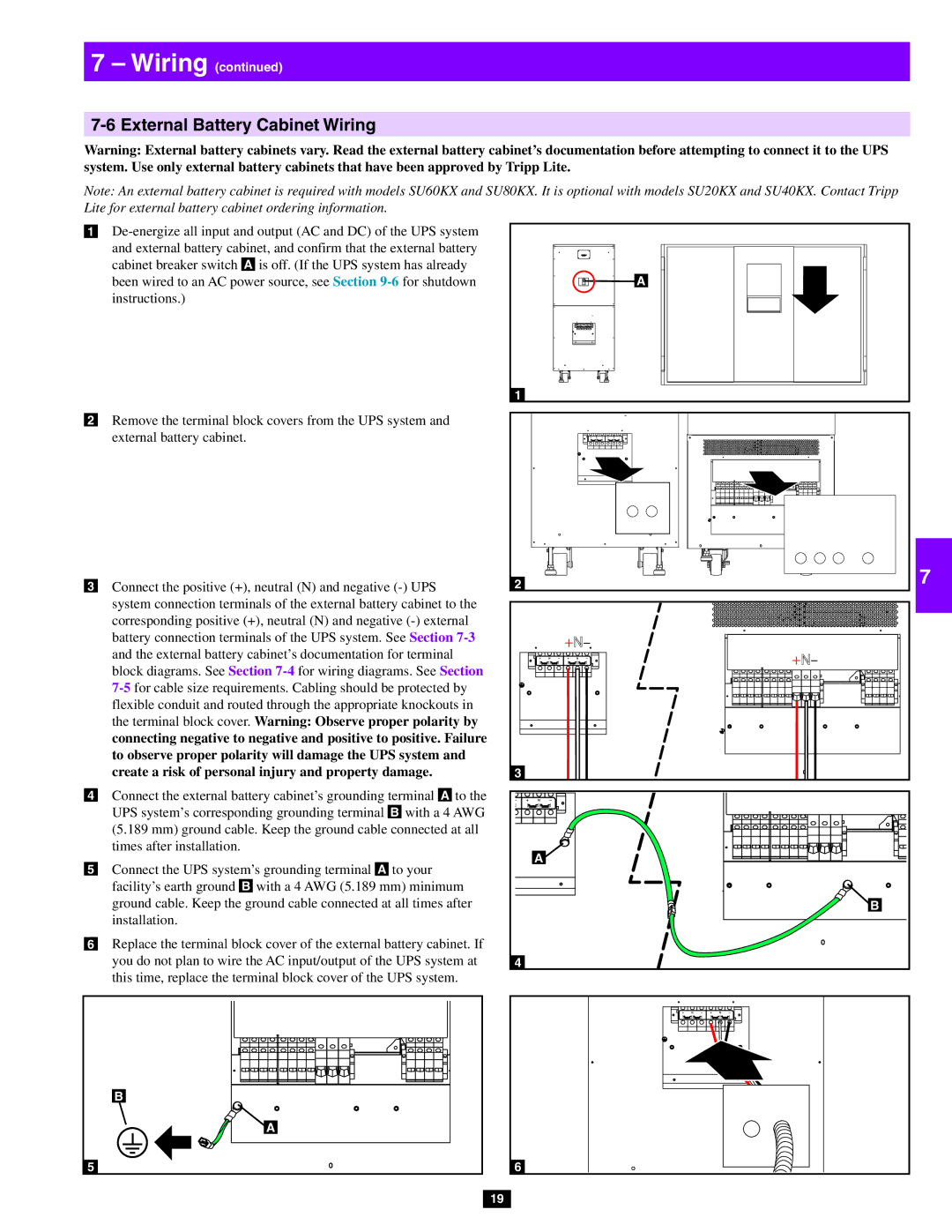
Failure to observe proper phase will damage the UPS system
7-7 AC Input/Output Wiring Single UPS
1 7 - Wiring continued
phase rotation by connecting R to R, S to S, T to T and N to N
Parallel configuration only supports 2 UPS systems 1+1
7-8 AC Input/Output Wiring Parallel UPS - Single Input Source
7 - Wiring continued
sharing between two UPS systems under reserve mode
10 8-4 Manual Bypass Mode Single UPS
8-1 Online Normal Mode Single UPS
8-2 Battery Backup Mode Single UPS
8-3 Auto Bypass Mode Single UPS
8 - Operating Modes continued
8-5 Online Mode Parallel UPS
8-6 Battery Backup Mode Parallel UPS
8-7 Auto Bypass Mode Parallel UPS
6 8-9 Hot Standby Mode Parallel UPS
8-8 Manual Bypass Mode Parallel UPS
1 8 - Operating Modes continued
9 - Start-Up, Shutdown and Bypass
9-1 Control Panel and Breaker Diagrams
9-2 Preliminary Checklist Single UPS
9-3 Standard Start-Up Procedure Single UPS
8 9-4 Battery Start-Up Procedure Single UPS
9-3 Standard Start-Up Procedure Single UPS continued
1 9 - Start-Up, Shutdown and Bypass continued
9-6 Shutdown Procedure Single UPS
9-5 Manual Bypass Procedure Single UPS
9 - Start-Up, Shutdown and Bypass continued
1 9 - Start-Up, Shutdown and Bypass continued
9-6 Shutdown Procedure Single UPS continued
9-7 Preliminary Checklist Parallel UPS
To transfer the critical load to NORMAL mode from Manual
9-8 Start-Up Procedure Parallel UPS continued
9-8 Start-Up Procedure Parallel UPS
9 - Start-Up, Shutdown and Bypass continued
1 9 - Start-Up, Shutdown and Bypass continued
9-9 Shutdown Procedure Parallel UPS
9 - Start-Up, Shutdown and Bypass continued
9-10 Manual Bypass Procedure Parallel UPS
maintenance or repair. Note Qualified service personnel may
local codes and the nature of the maintenance or repair
of each battery pack. On the SU20KX or SU40KX, turn OFF the
9-11 Switching from Manual Bypass to Normal Mode Parallel UPS
1 9 - Start-Up, Shutdown and Bypass continued
A “NORMAL” Green LED Illuminated when the UPS input B power is normal
10 - Display and Configuration
10-1 Control Panel Diagram
10-2 Display Hierarchy
10-3 Default Display
1 10 - Display and Configuration continued
10-3-1 Status Display
10-3-1 Status Display continued
10 - Display and Configuration continued
6 The UPS is in battery backup mode. The loads are supplied by
1 10 - Display and Configuration continued
equipment loads will receive battery backup power if the mains
utility or generator power source fails
10-3-1 Status Display continued
10-4 Main Menu
10 - Display and Configuration continued
8 The UPS system is operating in economy mode, and connected equipment loads are being powered by the bypass source
1 10 - Display and Configuration continued
10-4 Main Menu continued
UPS System “Measure Menu
ADMINISTRATOR Qualified service personnel User
10-5 UPS Setup
10 - Display and Configuration continued
Before changing the setting of each SETUP, you have to login first
If the password is wrong, press ” ” to reselect
10-5 UPS Setup continued
10-5-1 Bypass Setup
1 10 - Display and Configuration continued
10 - Display and Configuration continued
10-5-1 Bypass Setup continued
Press “ESC” to return to the “UPS SETUP” menu
10-5-2 Output Setup
1 10 - Display and Configuration continued
10-5-2 Output Setup continued
2 Output Voltage
Press “ESC” to return to the “UPS SETUP” menu
10-5-3 Battery Setup
10 - Display and Configuration continued
10-5-2 Output Setup continued
1 10 - Display and Configuration continued
10-5-3 Battery Setup continued
10 3 Battery Strings
5 Battery Next Replace Date
10 - Display and Configuration continued
10-5-3 Battery Setup continued
Press “ESC” to return to the “UPS SETUP” menu
to confirm the setting. Note The default charger current
10-5-4 Charger Setup
1 10 - Display and Configuration continued
Press “ESC” to return to the “UPS SETUP” menu
2 Parallel Group
10-5-5 Parallel Setup
10 - Display and Configuration continued
Press “ESC” to return to the “UPS SETUP” menu
3 Buzzer
10-5-6 Control & Test Setup
1 10 - Display and Configuration continued
2 Battery Auto Test
6 Clear Battery Test Result
10-5-6 Control & Test Setup continued
10 - Display and Configuration continued
4 Manual Battery Test
Press “ESC” to return to the “UPS SETUP” menu
10-5-7 Local Setup
1 10 - Display and Configuration continued
10-5-6 Control & Test Setup continued
5 LCD Contrast
10-5-7 Local Setup continued
10 - Display and Configuration continued
3 Date Format
6 Administrator Password
1 10 - Display and Configuration continued
10-5-7 Local Setup continued
Press “ESC” to return to the “UPS SETUP” menu
3 Statistics
10-6 Maintenance
10 - Display and Configuration continued
2 Firmware Version
Event Log
10-6 Maintenance continued
1 10 - Display and Configuration continued
Press “ESC” to return to the “UPS SETUP” menu
11-3 Input Dry Contact Interface
11 - Communications
11-1 Communications Interfaces
11-2 SNMPWEBCARD Slot
11-7 External Battery Status Input
11-4 Remote Emergency Power Off EPO Circuit Diagram
11-5 Auxiliary Dry Contact Input Circuit Diagram
11-6 External Battery Cabinet Temperature Inputs
Optional Messages
Default Messages
11 - Communications continued
11-8 Output Dry Contact Interface Detail
1 11 - Communications continued
11-9 Output Dry Contact Circuit Diagram
11-10 RS-232 Serial Port Circuit Diagram
11-11 Parallel Configuration Port
12-2 UPS System Floor Loading Table
12 - Specifications
12-1 UPS System Technical Specifications Optional Messages
12-3 Battery Pack Floor Loading Table
Note on Labeling
1 13 - Storage and Service
7 14 - Warranty
3 Service