7 – Wiring (continued) | 1 | |
| ||
|
| |
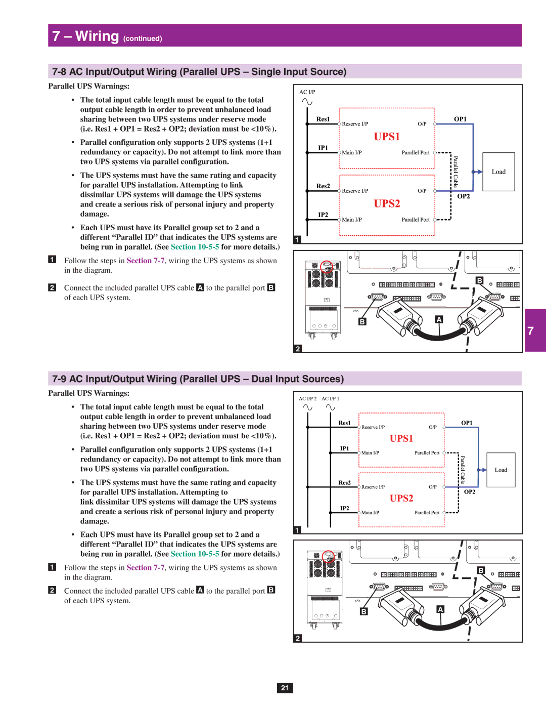
Parallel UPS Warnings: | 2 | |
• The total input cable length must be equal to the total | ||
| ||
output cable length in order to prevent unbalanced load |
| |
sharing between two UPS systems under reserve mode |
| |
(i.e. Res1 + OP1 = Res2 + OP2; deviation must be <10%). |
| |
• Parallel configuration only supports 2 UPS systems (1+1 | 3 | |
redundancy or capacity). Do not attempt to link more than |
| |
two UPS systems via parallel configuration. |
| |
• The UPS systems must have the same rating and capacity |
| |
for parallel UPS installation. Attempting to link | 4 | |
dissimilar UPS systems will damage the UPS systems | ||
| ||
and create a serious risk of personal injury and property |
| |
damage. |
|
| • Each UPS must have its Parallel group set to 2 and a |
|
|
| 5 |
| different “Parallel ID” that indicates the UPS systems are | 1 |
|
| |
| being run in parallel. (See Section |
|
|
|
|
•1 | Follow the steps in Section |
|
|
|
|
| in the diagram. |
|
|
|
|
•2 | Connect the included parallel UPS cable A to the parallel port B |
|
| B | 6 |
|
|
| |||
| of each UPS system. |
|
|
|
|
|
|
| B | A | 7 |
|
|
|
| ||
|
|
|
|
| |
|
| 2 |
|
|
|
|
|
| 8 | ||
Parallel UPS Warnings:
•The total input cable length must be equal to the total output cable length in order to prevent unbalanced load sharing between two UPS systems under reserve mode (i.e. Res1 + OP1 = Res2 + OP2; deviation must be <10%).
•Parallel configuration only supports 2 UPS systems (1+1 redundancy or capacity). Do not attempt to link more than two UPS systems via parallel configuration.
•The UPS systems must have the same rating and capacity for parallel UPS installation. Attempting to
link dissimilar UPS systems will damage the UPS systems and create a serious risk of personal injury and property damage.
•Each UPS must have its Parallel group set to 2 and a different “Parallel ID” that indicates the UPS systems are being run in parallel. (See Section
•1 Follow the steps in Section
•2 Connect the included parallel UPS cable A to the parallel port B of each UPS system.
|
| 9 |
|
| 10 |
1 |
| 11 |
|
| |
| B | 12 |
B | A | 13 |
| ||
|
| |
2 |
|
|
|
| 14 |
21