4 – Front and Rear Panel Features
1
A
B
C |
|
E | F |
D | G |
H ![]()
![]() H
H
I | I |
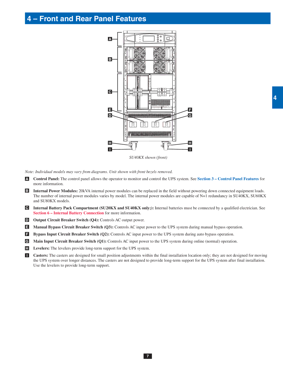
SU40KX shown (front)
Note: Individual models may vary from diagrams. Unit shown with front bezels removed.
•A Control Panel: The control panel allows the operator to monitor and control the UPS system. See Section 3 – Control Panel Features for more information.
•B Internal Power Modules: 20kVA internal power modules can be replaced in the field without powering down connected equipment loads. The number of internal power modules varies by model. The internal power modules are capable of N+1 redundancy in SU40KX, SU60KX and SU80KX models.
•C Internal Battery Pack Compartment (SU20KX and SU40KX only;): Internal batteries must be connected by a qualified electrician. See Section 6 – Internal Battery Connection for more information.
•D Output Circuit Breaker Switch (Q4): Controls AC output power.
•E Manual Bypass Circuit Breaker Switch (Q3): Controls AC input power to the UPS system during manual bypass operation.
•F Bypass Input Circuit Breaker Switch (Q2): Controls AC input power to the UPS system during auto bypass operation.
•G Main Input Circuit Breaker Switch (Q1): Controls AC input power to the UPS system during online (normal) operation.
•H Levelers: The levelers provide
•I Casters: The casters are designed for small position adjustments within the final installation location only; they are not designed for moving the UPS system over longer distances. The casters are not designed to provide
7
2
3
4
5
6
7
8
9
10
11
12
13
14
