19 – Start-Up, Shutdown and Bypass (continued)
9-11 Switching from Manual Bypass to Normal Mode (Parallel UPS)
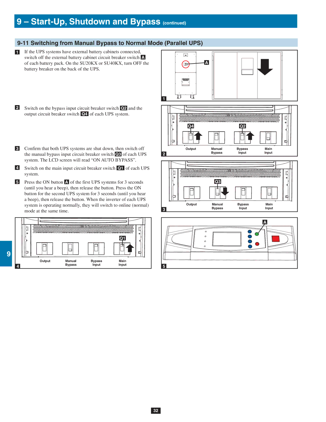
2 | •1 | If the UPS systems have external battery cabinets connected, | |||
| switch off the external battery cabinet circuit breaker switch A | ||||
|
| of each battery pack. On the SU20KX or SU40KX, turn OFF the | |||
|
| battery breaker on the back of the UPS. |
| ||
3 |
|
|
|
|
|
4 | •2 | Switch on the bypass input circuit breaker switch Q2 and the | |||
| output circuit breaker switch | Q4 of each UPS system. | |||
5 |
|
|
|
|
|
| •3 Confirm that both UPS systems are shut down, then switch off | ||||
|
| the manual bypass input circuit breaker switch Q3 of each UPS | |||
|
| system. The LCD screen will read “ON AUTO BYPASS”. | |||
6 | •4 | Switch on the main input circuit breaker switch Q1 of each UPS | |||
|
| system. |
|
|
|
| •5 | Press the ON button A of the first UPS systems for 3 seconds | |||
|
| (until you hear a beep), then release the button. Press the ON | |||
7 |
| button for the second UPS system for 3 seconds (until you hear | |||
| a beep), then release the button. When the inverter of each UPS | ||||
|
| system is operating normally, they will switch to online (normal) | |||
|
| mode at the same time. |
|
| |
8 |
|
|
|
|
|
|
|
|
|
| Q1 |
9 |
|
|
|
|
|
|
| Output | Manual | Bypass | Main |
| 4 |
| Bypass | Input | Input |
|
|
|
|
| |
![]() A
A
1 |
|
|
|
Q4 |
| Q2 |
|
Output | Manual | Bypass | Main |
2 | Bypass | Input | Input |
|
|
|
| Q3 |
|
|
Output | Manual | Bypass | Main |
3 | Bypass | Input | Input |
|
|
| |
|
|
| A |
5
10
11
12
13
14
32
