110 – Display and Configuration (continued)
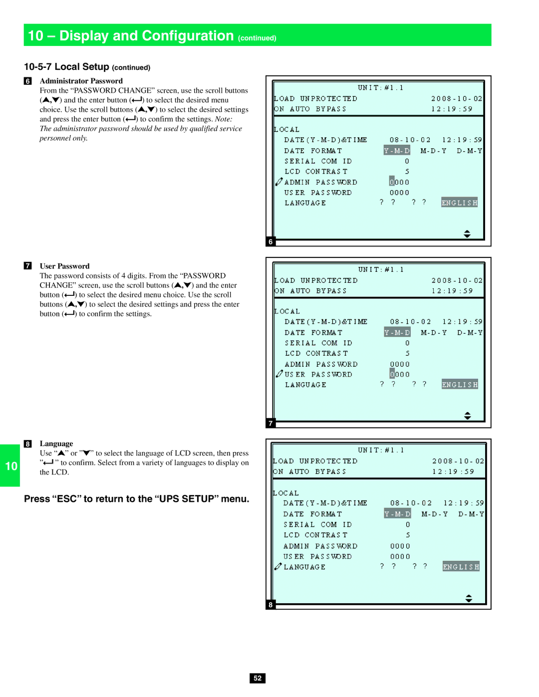
6Administrator Password
2 | From the “PASSWORD CHANGE” screen, use the scroll buttons | ||
( , ) and the enter button ( | ) to select the desired menu | ||
| |||
| choice. Use the scroll buttons ( | , ) to select the desired settings | |
| and press the enter button ( ) to confirm the settings. Note: | ||
| |||
3 | The administrator password should be used by qualified service | ||
personnel only. |
| ||
|
|
| |
|
|
| |
4 |
|
| |
|
|
| |
|
|
| |
5 |
|
| |
|
|
| |
7User Password
6 | The password consists of 4 digits. From the “PASSWORD | ||
CHANGE” screen, use the scroll buttons ( , ) and the enter | |||
| |||
| button ( | ) to select the desired menu choice. Use the scroll | |
| buttons ( | , ) to select the desired settings and press the enter | |
| button ( | ) to confirm the settings. | |
7
8
9
8Language
Use “![]() ” or ”
” or ”![]() ” to select the language of LCD screen, then press
” to select the language of LCD screen, then press
10 ”![]() ” to confirm. Select from a variety of languages to display on the LCD.
” to confirm. Select from a variety of languages to display on the LCD.
6
7
Press “ESC” to return to the “UPS SETUP” menu.
11
12
138
14
52