11 – Communications
1
Note: The communications connections described in this section are optional. The UPS system will function properly without these connections.
| 2 |
SNMPWEBCARD Slot
3
4
5
Input Dry Contact
Interface
|
|
|
|
|
|
|
|
|
|
|
|
|
|
|
|
|
|
|
|
|
|
|
|
|
|
|
|
|
|
|
|
|
|
|
|
|
|
|
|
|
|
|
|
|
|
|
|
|
|
|
|
|
|
|
|
|
|
|
|
|
|
|
|
Parallel |
|
|
| Output |
| Dry |
| ||||||||
Configuration Port |
|
|
|
|
| Serial Port | |||||||||
| Contact Interface |
| |||||||||||||
|
|
|
|
|
| ||||||||||
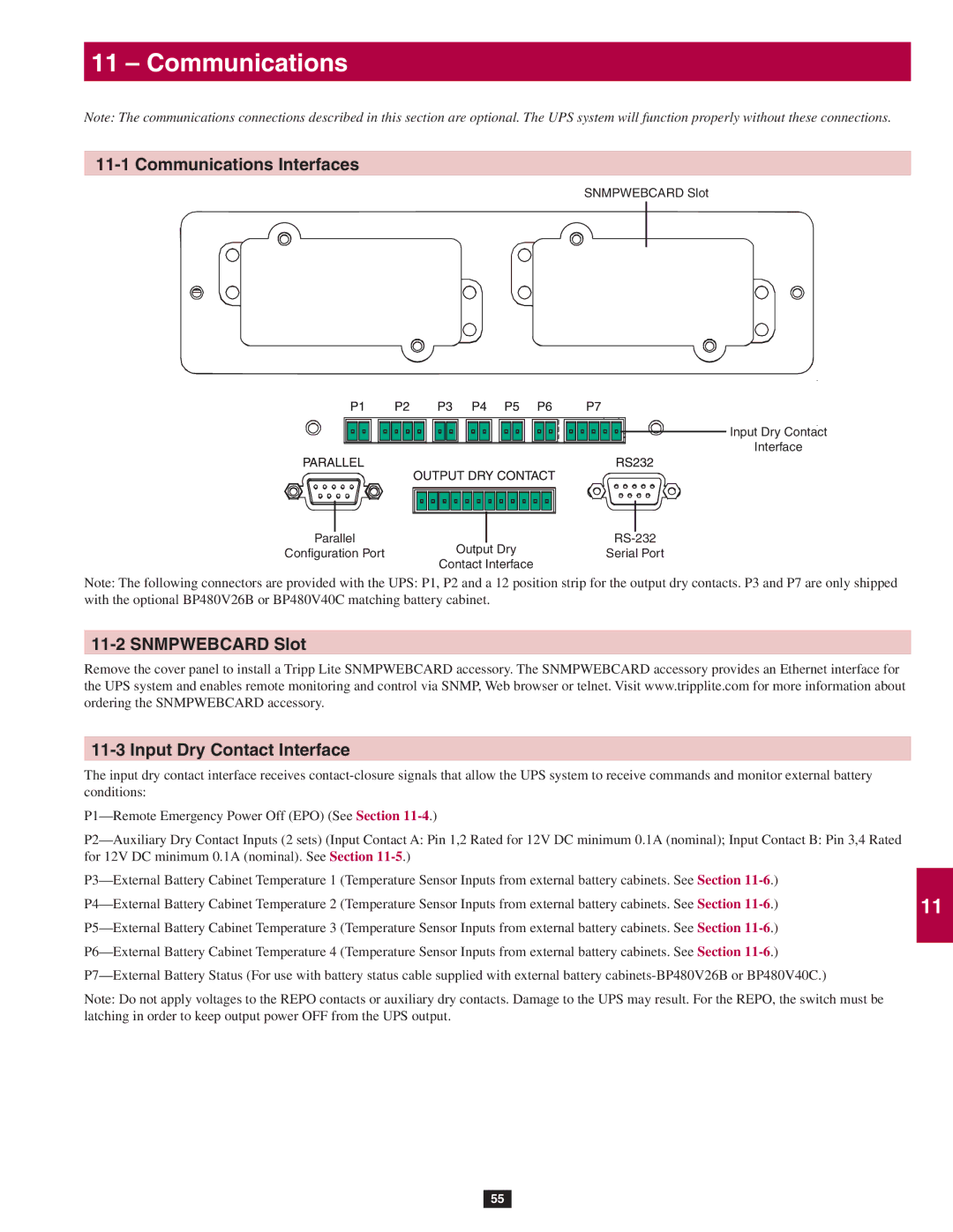
Note: The following connectors are provided with the UPS: P1, P2 and a 12 position strip for the output dry contacts. P3 and P7 are only shipped with the optional BP480V26B or BP480V40C matching battery cabinet.
11-2 SNMPWEBCARD Slot
Remove the cover panel to install a Tripp Lite SNMPWEBCARD accessory. The SNMPWEBCARD accessory provides an Ethernet interface for the UPS system and enables remote monitoring and control via SNMP, Web browser or telnet. Visit www.tripplite.com for more information about ordering the SNMPWEBCARD accessory.
11-3 Input Dry Contact Interface
The input dry contact interface receives
Note: Do not apply voltages to the REPO contacts or auxiliary dry contacts. Damage to the UPS may result. For the REPO, the switch must be latching in order to keep output power OFF from the UPS output.
55
6
7
8
9
10
11
12
13
14
