Owner’s Manual
Input/Output 220/380V, 230/400V or 240/415V AC, 3O, 4-wire + ground
Models SU20KX, SU40KX, SU60KX, SU80KX
Not suitable for mobile applications
1 Table of Contents
Advanced Features
1 - Introduction
Location Warnings
1 2 - Important Safety Instructions
SAVE THESE INSTRUCTIONS
Connection Warnings
Wiring Warnings
2 - Important Safety Instructions
Battery Warnings
1 3 - Control Panel Features
SU40KX shown front
4 - Front and Rear Panel Features
D Output Circuit Breaker Switch Q4 Controls AC output power
Levelers The levelers provide long-term support for the UPS system
5-2 Unpacking
5 - Cabinet Installation
5-1 Preparation
Read Section 2 - Important Safety Instructions Before Installation
the shipping container. Warning The UPS system could tip if it
1 5 - Cabinet Installation continued
5-3 Placement
is moved over an unstable surface. Be extremely careful when
SU40KX shown
6-1 Internal Battery Wiring Diagrams
DANGER! LETHAL HIGH VOLTAGE HAZARD
SU40KX shown
Battery Back
1 6 - Internal Battery Connection continued
6-1 Internal Battery Wiring Diagrams continued
Connector
6 - Internal Battery Connection continued
6-2 Internal Battery Connection Procedure
Warning Battery cartridge fuses must be inserted last due to
1 6 - Internal Battery Connection continued
6-2 Internal Battery Connection Procedure continued
potential arcing of connectors. Blown fuses must be replaced
13 Replace the battery access bezels
6 - Internal Battery Connection continued
6-2 Internal Battery Connection Procedure continued
7-2 Wiring Preparation
1 7 - Wiring
7-1 Wiring Warnings
DANGER! LETHAL HIGH VOLTAGE HAZARD
7-4 External Battery Cabinet Wiring Diagrams
7 - Wiring continued
7-3 UPS System Terminal Block Diagram
External Battery Cabinet Breaker Switch
7-5 Electrical and Cable Data
1 7 - Wiring continued
7-4 External Battery Cabinet Wiring Diagrams continued
External Battery Cabinets
7-6 External Battery Cabinet Wiring
7 - Wiring continued
phase rotation by connecting R to R, S to S, T to T and N to N
7-7 AC Input/Output Wiring Single UPS
1 7 - Wiring continued
Failure to observe proper phase will damage the UPS system
sharing between two UPS systems under reserve mode
7-8 AC Input/Output Wiring Parallel UPS - Single Input Source
7 - Wiring continued
Parallel configuration only supports 2 UPS systems 1+1
8-3 Auto Bypass Mode Single UPS
8-1 Online Normal Mode Single UPS
8-2 Battery Backup Mode Single UPS
10 8-4 Manual Bypass Mode Single UPS
8-7 Auto Bypass Mode Parallel UPS
8-5 Online Mode Parallel UPS
8-6 Battery Backup Mode Parallel UPS
8 - Operating Modes continued
1 8 - Operating Modes continued
8-8 Manual Bypass Mode Parallel UPS
6 8-9 Hot Standby Mode Parallel UPS
9-3 Standard Start-Up Procedure Single UPS
9-1 Control Panel and Breaker Diagrams
9-2 Preliminary Checklist Single UPS
9 - Start-Up, Shutdown and Bypass
1 9 - Start-Up, Shutdown and Bypass continued
9-3 Standard Start-Up Procedure Single UPS continued
8 9-4 Battery Start-Up Procedure Single UPS
9 - Start-Up, Shutdown and Bypass continued
9-5 Manual Bypass Procedure Single UPS
9-6 Shutdown Procedure Single UPS
To transfer the critical load to NORMAL mode from Manual
9-6 Shutdown Procedure Single UPS continued
9-7 Preliminary Checklist Parallel UPS
1 9 - Start-Up, Shutdown and Bypass continued
9 - Start-Up, Shutdown and Bypass continued
9-8 Start-Up Procedure Parallel UPS
9-8 Start-Up Procedure Parallel UPS continued
9-9 Shutdown Procedure Parallel UPS
1 9 - Start-Up, Shutdown and Bypass continued
local codes and the nature of the maintenance or repair
9-10 Manual Bypass Procedure Parallel UPS
maintenance or repair. Note Qualified service personnel may
9 - Start-Up, Shutdown and Bypass continued
1 9 - Start-Up, Shutdown and Bypass continued
9-11 Switching from Manual Bypass to Normal Mode Parallel UPS
of each battery pack. On the SU20KX or SU40KX, turn OFF the
10-2 Display Hierarchy
10 - Display and Configuration
10-1 Control Panel Diagram
A “NORMAL” Green LED Illuminated when the UPS input B power is normal
10-3-1 Status Display
1 10 - Display and Configuration continued
10-3 Default Display
10 - Display and Configuration continued
10-3-1 Status Display continued
utility or generator power source fails
1 10 - Display and Configuration continued
equipment loads will receive battery backup power if the mains
6 The UPS is in battery backup mode. The loads are supplied by
8 The UPS system is operating in economy mode, and connected equipment loads are being powered by the bypass source
10-4 Main Menu
10 - Display and Configuration continued
10-3-1 Status Display continued
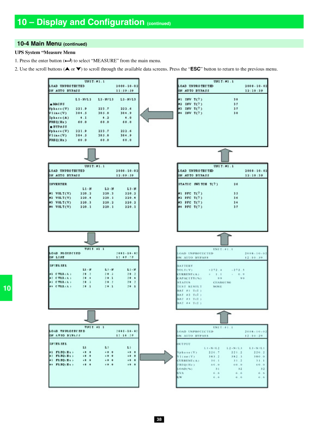
UPS System “Measure Menu
10-4 Main Menu continued
1 10 - Display and Configuration continued
Before changing the setting of each SETUP, you have to login first
10-5 UPS Setup
10 - Display and Configuration continued
ADMINISTRATOR Qualified service personnel User
1 10 - Display and Configuration continued
10-5 UPS Setup continued
10-5-1 Bypass Setup
If the password is wrong, press ” ” to reselect
10-5-2 Output Setup
10-5-1 Bypass Setup continued
Press “ESC” to return to the “UPS SETUP” menu
10 - Display and Configuration continued
2 Output Voltage
10-5-2 Output Setup continued
1 10 - Display and Configuration continued
10-5-2 Output Setup continued
10-5-3 Battery Setup
10 - Display and Configuration continued
Press “ESC” to return to the “UPS SETUP” menu
10 3 Battery Strings
10-5-3 Battery Setup continued
1 10 - Display and Configuration continued
Press “ESC” to return to the “UPS SETUP” menu
10 - Display and Configuration continued
10-5-3 Battery Setup continued
5 Battery Next Replace Date
Press “ESC” to return to the “UPS SETUP” menu
10-5-4 Charger Setup
1 10 - Display and Configuration continued
to confirm the setting. Note The default charger current
Press “ESC” to return to the “UPS SETUP” menu
10-5-5 Parallel Setup
10 - Display and Configuration continued
2 Parallel Group
2 Battery Auto Test
10-5-6 Control & Test Setup
1 10 - Display and Configuration continued
3 Buzzer
4 Manual Battery Test
10-5-6 Control & Test Setup continued
10 - Display and Configuration continued
6 Clear Battery Test Result
10-5-6 Control & Test Setup continued
10-5-7 Local Setup
1 10 - Display and Configuration continued
Press “ESC” to return to the “UPS SETUP” menu
3 Date Format
10-5-7 Local Setup continued
10 - Display and Configuration continued
5 LCD Contrast
Press “ESC” to return to the “UPS SETUP” menu
1 10 - Display and Configuration continued
10-5-7 Local Setup continued
6 Administrator Password
2 Firmware Version
10-6 Maintenance
10 - Display and Configuration continued
3 Statistics
Press “ESC” to return to the “UPS SETUP” menu
10-6 Maintenance continued
1 10 - Display and Configuration continued
Event Log
11-2 SNMPWEBCARD Slot
11 - Communications
11-1 Communications Interfaces
11-3 Input Dry Contact Interface
11-6 External Battery Cabinet Temperature Inputs
11-4 Remote Emergency Power Off EPO Circuit Diagram
11-5 Auxiliary Dry Contact Input Circuit Diagram
11-7 External Battery Status Input
11-8 Output Dry Contact Interface Detail
Default Messages
11 - Communications continued
Optional Messages
11-11 Parallel Configuration Port
11-9 Output Dry Contact Circuit Diagram
11-10 RS-232 Serial Port Circuit Diagram
1 11 - Communications continued
12-3 Battery Pack Floor Loading Table
12 - Specifications
12-1 UPS System Technical Specifications Optional Messages
12-2 UPS System Floor Loading Table
3 Service
1 13 - Storage and Service
7 14 - Warranty
Note on Labeling