XL-12000S
MANAGED, HIGH-SPEED NETWORK MODEM USER GUIDE
4.0Installation
1.Remove the modem and wall transformer from the shipping car- ton. Remove the wall transformer from its box. Remove the plastic wrapper from around the modem.
a.Remove the cable ties from each of the cables and place them side by side.
b.Each of the cables is identified as follows:
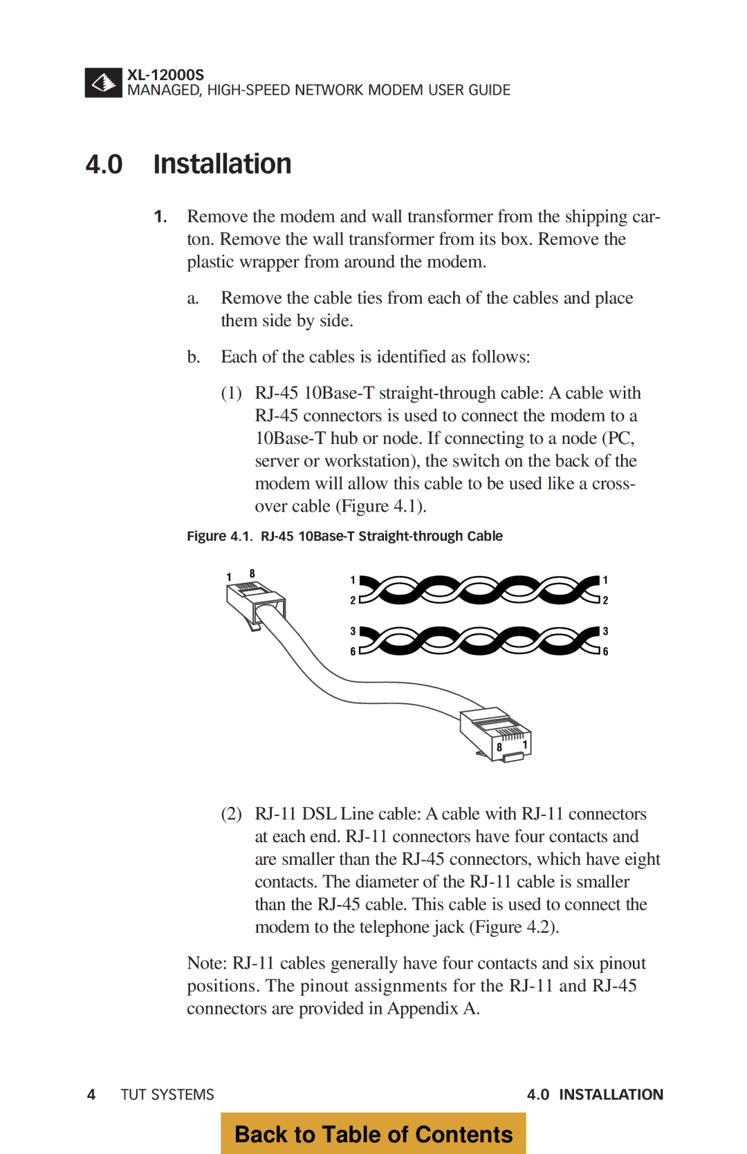
(1)RJ-45 10Base-T straight-through cable: A cable with RJ-45 connectors is used to connect the modem to a 10Base-T hub or node. If connecting to a node (PC, server or workstation), the switch on the back of the modem will allow this cable to be used like a cross- over cable (Figure 4.1).
Figure 4.1. RJ-45 10Base-T Straight-through Cable
8 1
(2)RJ-11 DSL Line cable: A cable with RJ-11 connectors at each end. RJ-11 connectors have four contacts and are smaller than the RJ-45 connectors, which have eight contacts. The diameter of the RJ-11 cable is smaller than the RJ-45 cable. This cable is used to connect the modem to the telephone jack (Figure 4.2).
Note: RJ-11 cables generally have four contacts and six pinout positions. The pinout assignments for the RJ-11 and RJ-45 connectors are provided in Appendix A.
4 TUT SYSTEMS | 4.0 INSTALLATION |
Back to Table of Contents