Operating Instructions
Series Amplifiers
Table of Contents
Setting
Dimensional Diagrams
Specifications
FCC Requirements
Important Safety Instructions
Safety Symbol and Message Conventions
Safety Precautions
When Installing the Unit
When the Unit is in Use
Over 10 cm
General Description
Features
Handling Precautions
Installation Precautions
Nomenclature and Functions
Unit indicator
Emergency indicator
Fault indicator
Input meter status indicator
Output level indication
Output meter status indicator
Output meter
Changing the indicated channels on the Level output meter
9060DH, A-9120DH, A-9120DL
9000
9060S, A-9120S
9240SH
Blank panel accessory
Mode switch
Preamplifier output Power amplifier input terminals
Speaker output terminal
1. D-001T 2-Channel Input Module
Optional Modules
Monaural input terminals 1
2. T-001T Audio Output Expansion Module
Control input terminal Contact
ZP-001T Zone Paging Module
Telephone input terminal TEL
Control input terminal in 1, 2, 3, 4, 5, 6, 7, 8, E
4. C-001T Control I/O Expansion Module
Control output terminal OUT 1, 2, 3, 4, 5, 6, 7, 8, E
AN-001T Ambient Noise Sensor Input Module
Front Side Rear
Optional Accessories
AN-9001 Ceiling Mount Microphone
Control output terminal E, OUT
ZM-9001 Zone Manager
Bottom Control buttons 1
ZM-9002 Zone Manager
Volume control
Description of Mixer Mode
Application example for a ball room, meeting room, etc
General Description
ANC Ambient Noise Control function AN-001T only
Glossary
Operation
Power ON/OFF
Basic Operation
Keys and knobs
Output channel ON/OFF
Changing the output parameters
Input channel ON/OFF
Recalling Scene Memory
Zone Paging
Paging port mode
Ring signal mode
Releasing Key Lock
Example when input keys are locked
Operation Example
Setting Menu Flow
Setting
Tip
Basic Setting Operation
Moving to setting screens
Setting content selection
Returning to the upper hierarchy level
Setting flow chart
Input Setting
43-A15
A1 Input gain setting
Input setting items
A2 Input channel name setting
1 I N
+ 1 2 0
HPF LPF
D E = P a G I N G P O R T
A14 Operation mode setting when the ZP-001T is used
M P L E T I M E
X I M U M L E V E L
I N R a T I O
C K E R O F F
A24 Ducker ON/OFF setting when the AN-001T is not used
C K E R P R I O R I T Y
Priority
Audio Output Setting
T 1 O U T
Speaker EQ settings
B5 Speaker parameter presetting
E Q = a L L F L a T
122SUBWFER*1
3SUBWOOFER*4
1SUBWOOFER*2
2SUBWOOFER*3
HX-5E LOCUT*8
SR-S4 SINGLE*6
B7 HPF and LPF settings F 4 0 0 H Z L P F 1
B9 Delay ON/OFF setting L a Y O F F
B8 Compressor setting M P R E S S O R O F F
Page
Interlock output control setting
Utility Setting
M a T T E N U a T E
G I N G O F F
N = 1 2 3 4 5 6 7 8 9 a B C
N 0 1 N O N E
N =
U T = 1 2 3 4 5 6 7 8 9 a B C
U T =
M O T E 1 V O L U M E
M O T E 1 O U T P U T
N S E L S Y N C O N
C19 Gate release time setting T E R E L E a S E T I M E
C18 Password setting
C20 Communication speed bps setting R I a L S P E E D = 5
C17 Lock status display Y L O C K U N L O C K E D
C23 Memory initialization I T I a L I Z E O K ?
C22 Firmware version indication R M V E R S I O N = 1.1
Paging function
Paging Setting
SP1 SP2 SP3 SP4
65-D2
G I N G T R I G Z P
Paging setting items
D1 Paging input channel setting G I N G O N I N
G I N G D I S a B L E O F F
G I N G S Y N C O F F
Control input terminal
When the control input function Is set to EMG-MUTE p -E16
Control Input Function Setting
N 0 1 L O a D B a N K
Control input function setting items
E1 Control input function setting N 0 1 N O N E
E9 Volume decreasing level setting N 0 1 V O L D O W N
E8 Volume increasing level setting
N 0 1 V O L U P
E11 Input/Output channel number selection N 0 1 C H O N
E17 Interlock output control setting
E14 Interlock output control setting
N 0 1 S Y N C
N 0 1 E M G M U T E
Page
Control Output Function Setting
F4 Scene memory bank number selection U T 0 1 S C E N E
Control output function setting items
F1 Control output function setting U T 0 1 N O N E
F6 Input/Output channel number selection U T 0 1 C H O N I N
Keys that can be locked
Key Lock Function Setting
ALL
Util
All-key lock ON/OFF p -G1
Y L O C K O U T P U T O F F
Y L O C K a L L O F F
Y L O C K I N P U T O F F
G7 Power switch lock ON/OFF
G6 Setting key lock ON/OFF
Y L O C K U T I L O F F
Y L O C K P O W E R O F F
Password setting
Key lock setting operation
Scene memory save p -H3
Memory Setting
V E
A D
E N E S E T T I N G S a V E
W E R O N L a S T S T a T E
H5 Scene memory erasure when Erase is set
A S E
Storing Scene Memory
HOW to Store or Erase Scene Memory
Press for over 2 seconds
Erasing Scene Memory
Setting the Scene Memory to be Recalled at Power-On
Restoring Factory Default Setting
Default Setting Table
ALL Flat
Audio output settings
Paging input settings
Utility settings
Trigger C-IN
Trigger VOX
Control output function setting
Control input function setting
Control input function Loadbank
Control input function Volup
Scene memory Save
Memory settings
Scene memory Erase
Scene memory P-ON
Module Installation
Module Installation
Module Combination
Channel Numbers and Terminal Numbers
Insert the C-001T module in the open slot
Module Installation Examples
Connections
Remote volumes 1
Control I/O Terminal Connections
Control inputs 1
Control outputs 1
Level trigger
Operation by control input Pulse trigger
Direct output terminal connection
100
Transformer output terminal connection
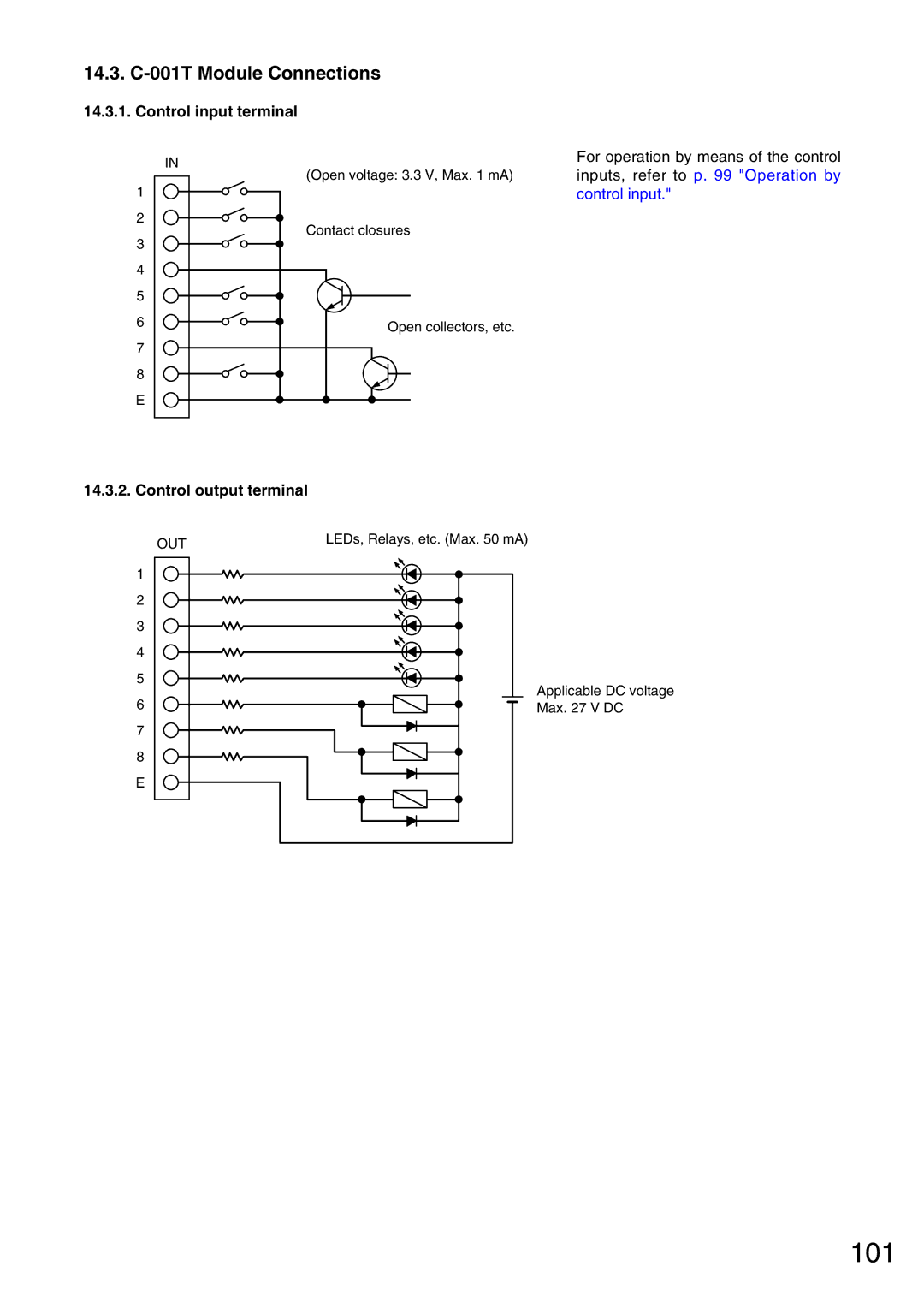
14.3. C-001T Module Connections
101
Control input terminal
Control output terminal
AN-001T and AN-9001 Connections
RS-232C Connector Connection
102
103
Connector connection
Removable Terminal Plug Connection
Cable end treatment
Rack Mounting Bracket Attachment
104
Tips
AN-9001 Installation
105
106
Dimensional Diagrams
AN-9001
Front Bottom
ZM-9001
107
ZM-9002
Front Bottom Front View without panel Side
System requirements
HOW to USE the Supplied Software
108
109
Installing the Software
Connecting the Unit to the PC
110
Setting the Communication Port and Speed
Updating the Firmware
111
112
Storing or Recalling Parameters Set at the Unit
113
114
Screen indications and their descriptions
115
Monitoring the Units Operation Status
116
Step
117
Activating the Control Input
118
Error Indications
119
Troubleshooting
120
Block Diagram
ZP-001T Zone Paging
Signal Flow Diagram
121
122
Level Diagram
ADC LPF
Slot
123
Specifications 24.1. M-9000
124
Accessories
24.2. A-9060DH, A-9120DH
125
126
24.3. A-9120DL
127
128
24.4. A-9060S, A-9120S
129
130
24.5. A-9240SH
131
132
Cmrr
133
24.6.1. D-001T
24.6.2. T-001T
134
ZP-001T
135
24.6.3. C-001T
AN-001T
136
AN-9001
137
ZM-9001
ZM-9002
200604