Controls and Functions
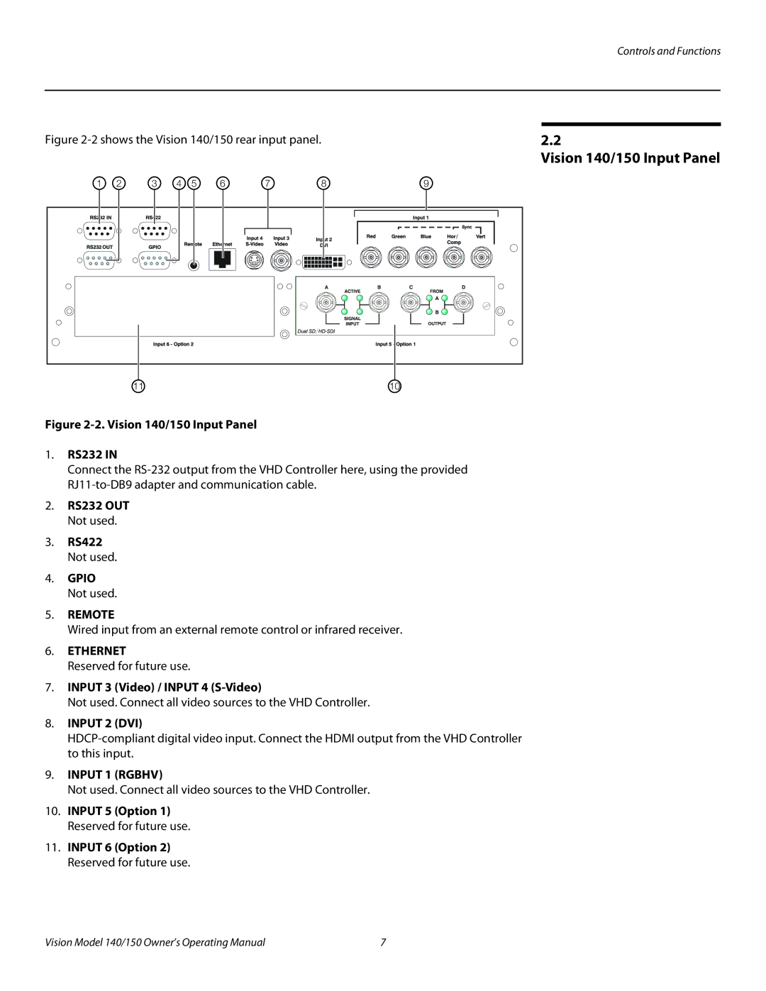
Figure 2-2 shows the Vision 140/150 rear input panel.
1 | 2 | 3 | 4 | 5 | 6 | 7 | 8 | 9 |
|
| 11 |
|
|
|
|
| 10 |
Figure 2-2. Vision 140/150 Input Panel
1.RS232 IN
Connect the
2.RS232 OUT Not used.
3.RS422 Not used.
4.GPIO Not used.
5.REMOTE
Wired input from an external remote control or infrared receiver.
6.ETHERNET
Reserved for future use.
7.INPUT 3 (Video) / INPUT 4
Not used. Connect all video sources to the VHD Controller.
8. INPUT 2 (DVI)
9.INPUT 1 (RGBHV)
Not used. Connect all video sources to the VHD Controller.
10.INPUT 5 (Option 1) Reserved for future use.
11.INPUT 6 (Option 2) Reserved for future use.
2.2
Vision 140/150 Input Panel
Vision Model 140/150 Owner’s Operating Manual | 7 |