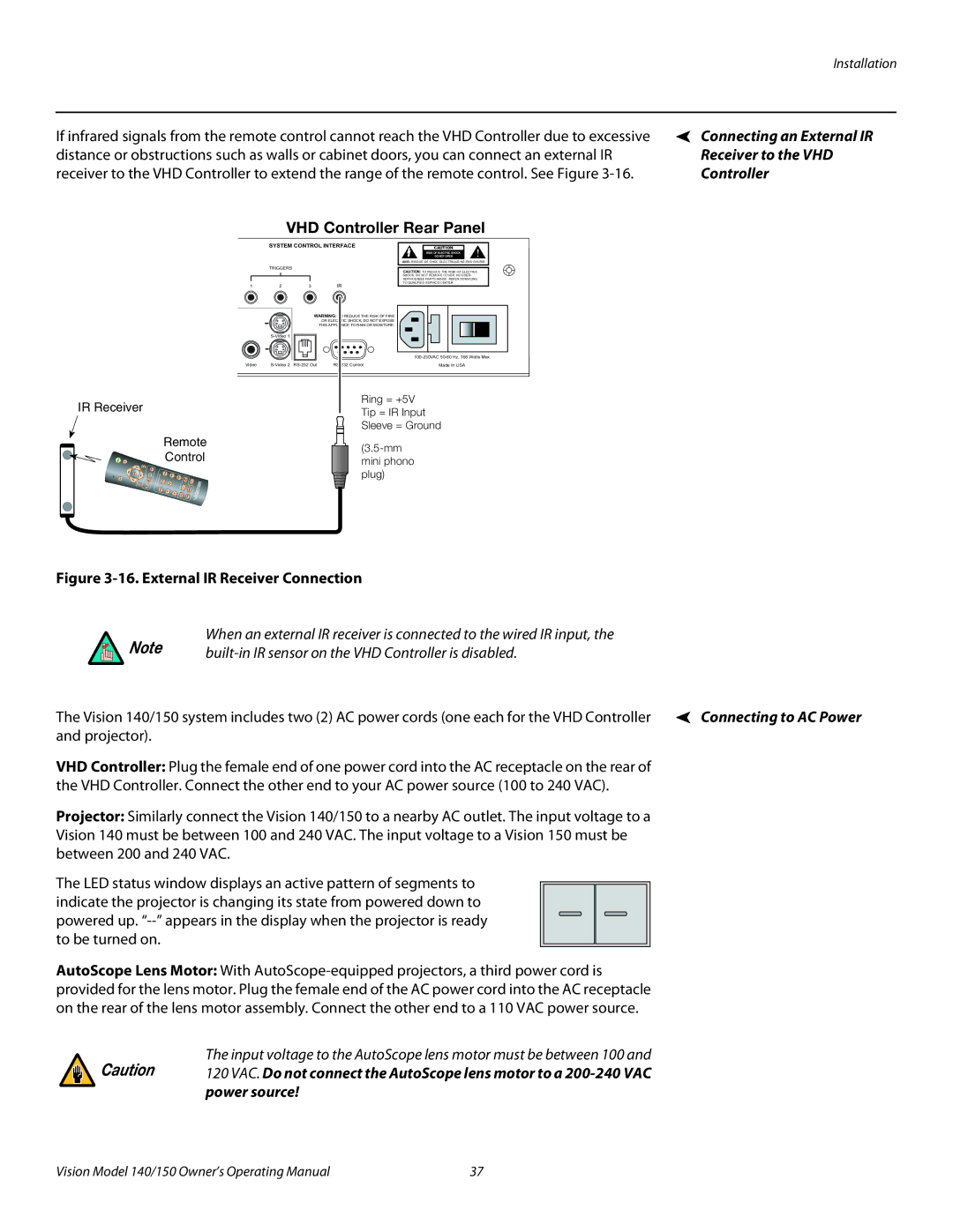
If infrared signals from the remote control cannot reach the VHD Controller due to excessive distance or obstructions such as walls or cabinet doors, you can connect an external IR receiver to the VHD Controller to extend the range of the remote control. See Figure
VHD Controller Rear Panel
SYSTEM CONTROL INTERFACE | CAUTION | ! |
| RISK OF ELECTRIC SHOCK | |
| DO NOT OPEN | |
| AVIS: RISQUE DE CHOC | |
TRIGGERS
CAUTION: TO REDUCE THE RISK OF ELECTRIC
SHOCK, DO NOT REMOVE COVER. NO USER-
SERVICEABLE PARTS INSIDE. REFER SERVICING
TO QUALIFIED SERVICE CENTER.
1 | 2 | 3 | IR |
WARNING: TO REDUCE THE RISK OF FIRE
OR ELECTRIC SHOCK, DO NOT EXPOSE
THIS APPLIANCE TO RAIN OR MOISTURE.
Video | Made In USA |
Ring = +5V
IR ReceiverTip = IR Input
Sleeve = Ground
Remote | ||
Control | ||
mini phono | ||
| ||
| plug) |
Connecting an External IR Receiver to the VHD Controller
Figure 3-16. External IR Receiver Connection
When an external IR receiver is connected to the wired IR input, the
Note |
| |
|
| |
The Vision 140/150 system includes two (2) AC power cords (one each for the VHD Controller | Connecting to AC Power | |
and projector). |
|
|
VHD Controller: Plug the female end of one power cord into the AC receptacle on the rear of the VHD Controller. Connect the other end to your AC power source (100 to 240 VAC).
Projector: Similarly connect the Vision 140/150 to a nearby AC outlet. The input voltage to a Vision 140 must be between 100 and 240 VAC. The input voltage to a Vision 150 must be between 200 and 240 VAC.
The LED status window displays an active pattern of segments to indicate the projector is changing its state from powered down to powered up.
AutoScope Lens Motor: With
Caution | The input voltage to the AutoScope lens motor must be between 100 and |
120 VAC. Do not connect the AutoScope lens motor to a | |
| power source! |
Vision Model 140/150 Owner’s Operating Manual | 37 |