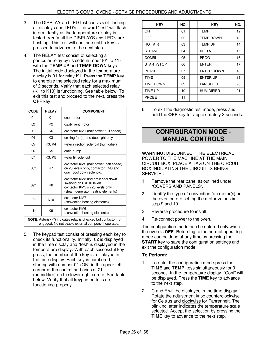
VCE10F 126179, VCE20F 126173, VCE6H 126177, VCE10H 126178, VCE20H 126172 specifications
The Vulcan-Hart VCE series consists of several efficient and powerful cooking equipment models, including the VCE20H 126172, VCE10H 126178, VCE6H 126177, VCE20F 126173, and VCE10F 126179. These models are designed to meet the rigorous demands of commercial kitchens and food service operations.The VCE20H 126172 is a versatile convection oven that offers a spacious cooking capacity, making it ideal for establishments with high-volume cooking needs. Its dual fan system ensures even heat distribution, which results in perfectly cooked dishes every time. This model features a digital control panel that allows for precise temperature adjustments and programmable cooking settings, enhancing overall operational efficiency.
Similarly, the VCE10H 126178 is a compact yet powerful option that accommodates smaller kitchens while still delivering outstanding performance. Its energy-efficient design minimizes power consumption without sacrificing output. The stainless steel construction ensures durability and easy maintenance, making it a reliable choice for busy culinary environments.
The VCE6H 126177 model is another compact oven designed for limited spaces while providing exceptional cooking capabilities. With its robust heating elements and efficient airflow system, it excels in baking and roasting tasks. Additionally, it features a user-friendly interface that simplifies the cooking process, enabling staff to focus on food quality and service speed.
The VCE20F 126173 stands out with its innovative technology, integrating a focused heating system that enhances cooking consistency and reduces cooking times. Ideal for frying, roasting, and baking, this model incorporates advanced safety features like automatic shut-off and temperature monitoring, ensuring a safe cooking environment.
Lastly, the VCE10F 126179 is perfect for establishments seeking a combination of performance and versatility. This model offers various cooking modes, allowing chefs to experiment with different techniques seamlessly. Its compact size makes it a great fit in kitchens with limited space, while the commercial-grade specifications guarantee long-lasting operation.
In conclusion, the Vulcan-Hart VCE series, featuring models like the VCE20H, VCE10H, VCE6H, VCE20F, and VCE10F, encompasses a range of options suitable for diverse commercial cooking needs. Each model is built with advanced technologies, emphasizing efficiency, safety, and durability, making them ideal choices for any professional kitchen. The carefully designed features of these ovens not only enhance cooking quality but also improve workflow, making them essential kitchen tools for culinary excellence.

