|
|
| Rear Support Continued... |
|
|
|
|
|
|
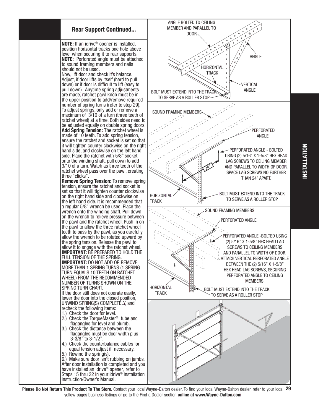
| NOTE: If an idrive® opener is installed, |
| Tools Needed: |
| |
|
| position horizontal tracks one hole above | |
|
|
| |
|
|
| level when securing it to rear supports. |
|
|
| |
|
|
| NOTE: Perforated angle must be attached |
|
|
| to sound framing members and nails |
|
|
| should not be used. |
|
|
| Now, lift door and check it’s balance. |
|
|
| Adjust, if door lifts by itself (hard to pull |
|
|
| down) or if door is difficult to lift (easy to |
|
|
| pull down). Anytime spring adjustments |
|
|
| are made, ratchet pawl knob must be in |
|
|
| the upper position to add/remove required |
|
|
| number of spring turns (refer to step 29). |
|
|
| To adjust springs, only add or remove a |
Angle bolted to ceiling member and parallel to door
Horizontal
track
Bolt must extend into the track to serve as a roller stop![]()
Angle
![]() Vertical Angle
Vertical Angle
maximum of 3/10 of a turn (three teeth of | |
ratchet wheel) at a time. Both sides need to | |
be adjusted equally on double spring doors. | |
Add Spring Tension: The ratchet wheel is | |
made of 10 teeth. To add spring tension, | |
ensure the ratchet and socket is set so that | |
it will tighten counter clockwise on the right | |
hand side, and clockwise on the left hand | |
side. Place the ratchet with 5/8” socket | |
onto the winding shaft, pull down to add | |
3/10 of a turn. Watch as three teeth of the | |
ratchet wheel pass over the pawl, creating | |
three “clicks”. | |
Remove Spring Tension: To remove spring | |
tension, ensure the ratchet and socket is | |
set so that it will tighten counter clockwise | |
on the right hand side and clockwise on | |
the left hand side. It is recommended that | |
a regular 5/8” wrench be used. Place the | |
wrench onto the winding shaft. Pull down | |
on the wrench to relieve pressure between | |
the pawl and the ratchet wheel. Push in on | |
the pawl to allow the three ratchet wheel | |
teeth to pass by the pawl, as you carefully | |
allow the wrench to be rotated upward by | |
the spring tension. Release the pawl to | |
allow it to engage with the ratchet wheel. | |
Important: BE PREPARED TO HOLD THE | |
FULL TENSION OF THE SPRING. | |
Important: DO NOT ADD OR REMOVE | |
MORE THAN 1 SPRING TURNS (1 SPRING | |
TURN EQUALS 10 TEETH ON RATCHET | |
WHEEL) FROM THE RECOMMENDED | |
NUMBER OF TURNS SHOWN ON THE | |
SPRING TURN CHART. | |
If the door still does not operate easily, | |
lower the door into the closed position, | |
UNWIND SPRING(S) COMPLETELY, and | |
recheck the following items: | |
1.) | Check the door for level. |
2.) | Check the TorqueMaster® tube and |
| flagangles for level and plumb. |
3.) | Check the distance between the |
| flagangles must be door width plus |
| |
4.) | Check the counterbalance cables for |
| equal tension adjust if necessary. |
5.) | Rewind the spring(s). |
6.) | Make sure door isn’t rubbing on jambs. |
After door installation is completed and you | |
have installed an idrive® opener, refer to | |
Steps 15 thru 32 in your idrive® Installation | |
Instruction/Owner’s Manual. | |
Sound Framing Members
Perforated
ANGLE
![]() Perforated ANGLE - BOLTED USING (2) 5/16” X
Perforated ANGLE - BOLTED USING (2) 5/16” X
LAG SCREWS TO CEILING MEMBER AND PARALLEL TO WIDTH OF DOOR. Space lag screws no further
than 24” apart.
HORIZONTAL | BOLT MUST EXTEND INTO THE TRACK | |
TO SERVE AS A ROLLER STOP | ||
TRACK | ||
| ||
|
| |
| Sound Framing Members |
PERFORATED ANGLE
Perforated ANGLE -BOLTED USING
(2) 5/16” X
AND PARALLEL TO WIDTH OF DOOR. Attach vertical perforated angle between the (2) 5/16” X
HORIZONTAL | BOLT MUST EXTEND INTO THE TRACK | |
TRACK | ||
TO SERVE AS A ROLLER STOP | ||
|
INSTALLATION
Please Do Not Return This Product To The Store. Contact your local
