|
| |
P2 | TorqueMaster® Spring Removal | |
Tools Needed: | A TorqueMaster® spring system can be | |
identified by the end brackets. For single | ||
| ||
Recommended | spring applications, the right hand end | |
bracket will always have a drive gear, | ||
tools from | counter gear, counter cover, and a winding | |
page 5 | bolt head. The left hand end bracket will | |
| have no gears, counter cover, or winding | |
| bolt head. The hole for the winding bolt | |
| head will be plugged. | |
| For double springs, both the right hand | |
| and left hand end brackets will always | |
| have a drive gear, counter gear, counter | |
| cover and a winding bolt head. | |
| IMPORTANT: Right and left hand is | |
| always determined from inside the | |
| building looking out. | |
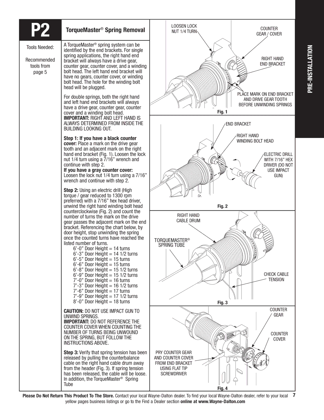
| Step 1: If you have a black counter | |
| cover: Place a mark on the drive gear | |
| tooth and an adjacent mark on the right | |
| hand end bracket (Fig. 1). Loosen the lock | |
| nut 1/4 turn using a 7/16” wrench and | |
| continue with step 2. | |
| If you have a gray counter cover: | |
| Loosen the lock nut 1/4 turn using a 7/16” | |
| wrench and continue with step 2. | |
| Step 2: Using an electric drill (High | |
| torque / gear reduced to 1300 rpm | |
| preferred) with a 7/16” hex head driver, | |
| unwind the right hand winding bolt head | |
| counterclockwise (Fig. 2) and count the | |
| number of turns the mark on the drive | |
| gear passes the adjacent mark on the end | |
| bracket. Referencing the chart below, by | |
| door height, stop unwinding the spring | |
| once the counted turns have reached the | |
| listed number of turns. | |
| ||
| ||
| ||
| ||
| ||
| ||
| ||
| ||
| ||
| ||
|
|
Loosen lock | Counter | |
nut 1/4 turn | ||
gear / cover | ||
|
Right hand
end bracket
Place mark on end bracket
and drive gear tooth
before unwinding springs
Fig. 1
End bracket
Right hand winding bolt head
Electric drill with 7/16” hex driver (do not use impact gun)
Fig. 2
Right hand cable drum
TorqueMaster®
Spring Tube
Check cable
![]() tension
tension
Fig. 3
PRE-INSTALLATION
CAUTION: DO NOT USE IMPACT GUN TO |
UNWIND SPRINGS. |
IMPORTANT: DO NOT reference the |
counter cover when counting the |
number of turns being unwound |
on the spring, but follow the |
instructions above. |
Step 3: Verify that spring tension has been |
released by pulling the counterbalance |
cable on the right hand cable drum away |
from the header (Fig. 3). If spring tension |
has been released, the cable will be loose. |
In addition, the TorqueMaster® Spring |
Tube |
Pry counter gear and counter cover from end bracket using flat Tip screwdriver
Counter
gear
Counter ![]() cover
cover
Fig. 4
Please Do Not Return This Product To The Store. Contact your local