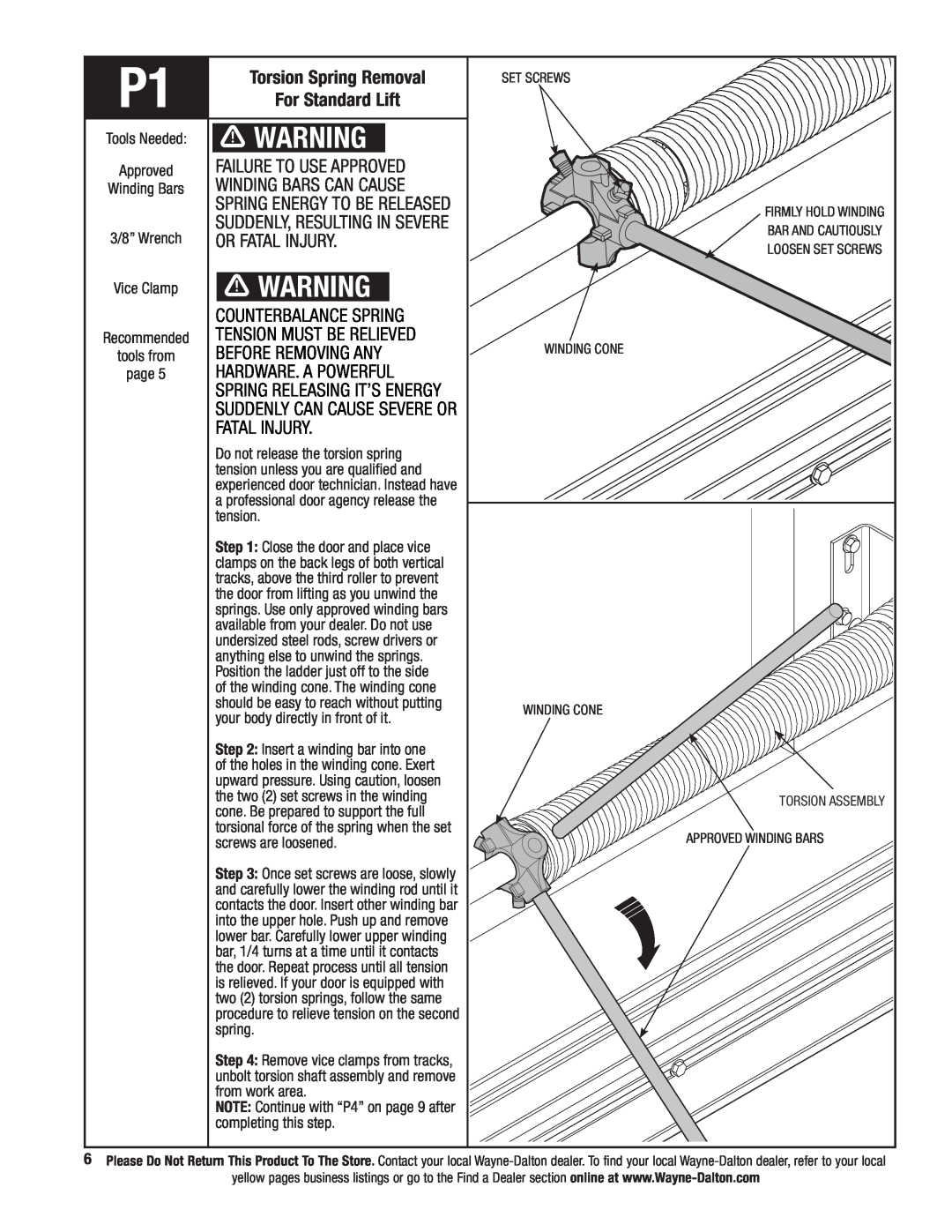
P1 | Torsion Spring Removal | SET SCREWS | |
For Standard Lift |
| ||
Tools Needed: | WARNING |
| |
Approved | Failure to use approved |
| |
Winding Bars | winding bars can cause |
| |
| spring energy to be released | Firmly hold winding | |
| suddenly, resulting in severe | ||
3/8” Wrench | bar and cautiously | ||
or fatal injury. | |||
loosen set screws | |||
|
| ||
Vice Clamp | WARNING |
| |
| COUNTERBALANCE SPRING |
| |
Recommended | TENSION MUST BE RELIEVED | Winding cone | |
tools from | BEFORE REMOVING ANY | ||
page 5 | HARDWARE. A POWERFUL |
| |
| SPRING RELEASING IT’S ENERGY |
| |
| SUDDENLY CAN CAUSE SEVERE OR |
| |
| FATAL INJURY. |
| |
| Do not release the torsion spring |
| |
| tension unless you are qualified and |
| |
| experienced door technician. Instead have |
| |
| a professional door agency release the |
| |
| tension. |
| |
| Step 1: Close the door and place vice |
| |
| clamps on the back legs of both vertical |
| |
| tracks, above the third roller to prevent |
| |
| the door from lifting as you unwind the |
| |
| springs. Use only approved winding bars |
| |
| available from your dealer. Do not use |
| |
| undersized steel rods, screw drivers or |
| |
| anything else to unwind the springs. |
| |
| Position the ladder just off to the side |
| |
| of the winding cone. The winding cone |
| |
| should be easy to reach without putting | WINDING CONE | |
| your body directly in front of it. | ||
|
| ||
| Step 2: Insert a winding bar into one |
| |
| of the holes in the winding cone. Exert |
| |
| upward pressure. Using caution, loosen |
| |
| the two (2) set screws in the winding | TORSION ASSEMBLY | |
| cone. Be prepared to support the full | ||
|
| ||
| torsional force of the spring when the set | APPROVED WINDING BARs | |
| screws are loosened. | ||
| Step 3: Once set screws are loose, slowly |
| |
| and carefully lower the winding rod until it |
| |
| contacts the door. Insert other winding bar |
| |
| into the upper hole. Push up and remove |
| |
| lower bar. Carefully lower upper winding |
| |
| bar, 1/4 turns at a time until it contacts |
| |
| the door. Repeat process until all tension |
| |
| is relieved. If your door is equipped with |
| |
| two (2) torsion springs, follow the same |
| |
| procedure to relieve tension on the second |
| |
| spring. |
| |
| Step 4: Remove vice clamps from tracks, |
| |
| unbolt torsion shaft assembly and remove |
| |
| from work area. |
| |
| NOTE: Continue with “P4” on page 9 after |
| |
| completing this step. |
|
6Please Do Not Return This Product To The Store. Contact your local
yellow pages business listings or go to the Find a Dealer section online at