User Guide | WireSpeed Dual Connect NAT Router |
5.5 LED Indicators
The LED indicators are used to verify the unit’s operation and status. LED states are described in Table 1.
Table 1. LED States and Descriptions
LED | State | Description | |
POWER | Solid Green | Power ON | |
No Light | No Power | ||
| |||
| Slow Flashing Green | Power ON and waiting for carrier detect signal | |
|
| (1 flash/sec) | |
| Moderate Flashing Green | Power ON and attempting synchronization | |
READY |
| (2 flashes/sec) | |
Solid Green | Power ON and synchronized with ADSL line card | ||
| Steady Red (less than 20 sec.) | Hardware | |
| Flashing Yellow | Modem failed | |
| Solid Yellow | Modem is in safe boot mode | |
| No Light | No Power | |
ETHERNET | Solid Green | Ethernet link established | |
Flashing Green | Transmit or Receive Activity | ||
| No Light | No link established | |
USB | Solid Green | USB link established | |
Flashing Green | Transmit or Receive Activity | ||
| No Light | No USB link established |
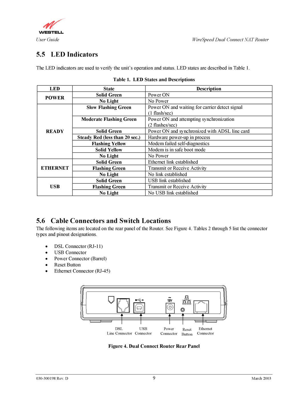
5.6 Cable Connectors and Switch Locations
The following items are located on the rear panel of the Router. See Figure 4. Tables 2 through 5 list the connector types and pinout designations.
•DSL Connector
•USB Connector
•Power Connector (Barrel)
•Reset Button
•Ethernet Connector
DSL | USB | Power | Reset | Ethernet |
Line Connector | Connector | Connector | Button | Connector |
Figure 4. Dual Connect Router Rear Panel
9 | March 2003 |