8.After feeding cable to where you are going to install the positioner, strip 3/8" insulation off all wires in the 13 cable bundle.
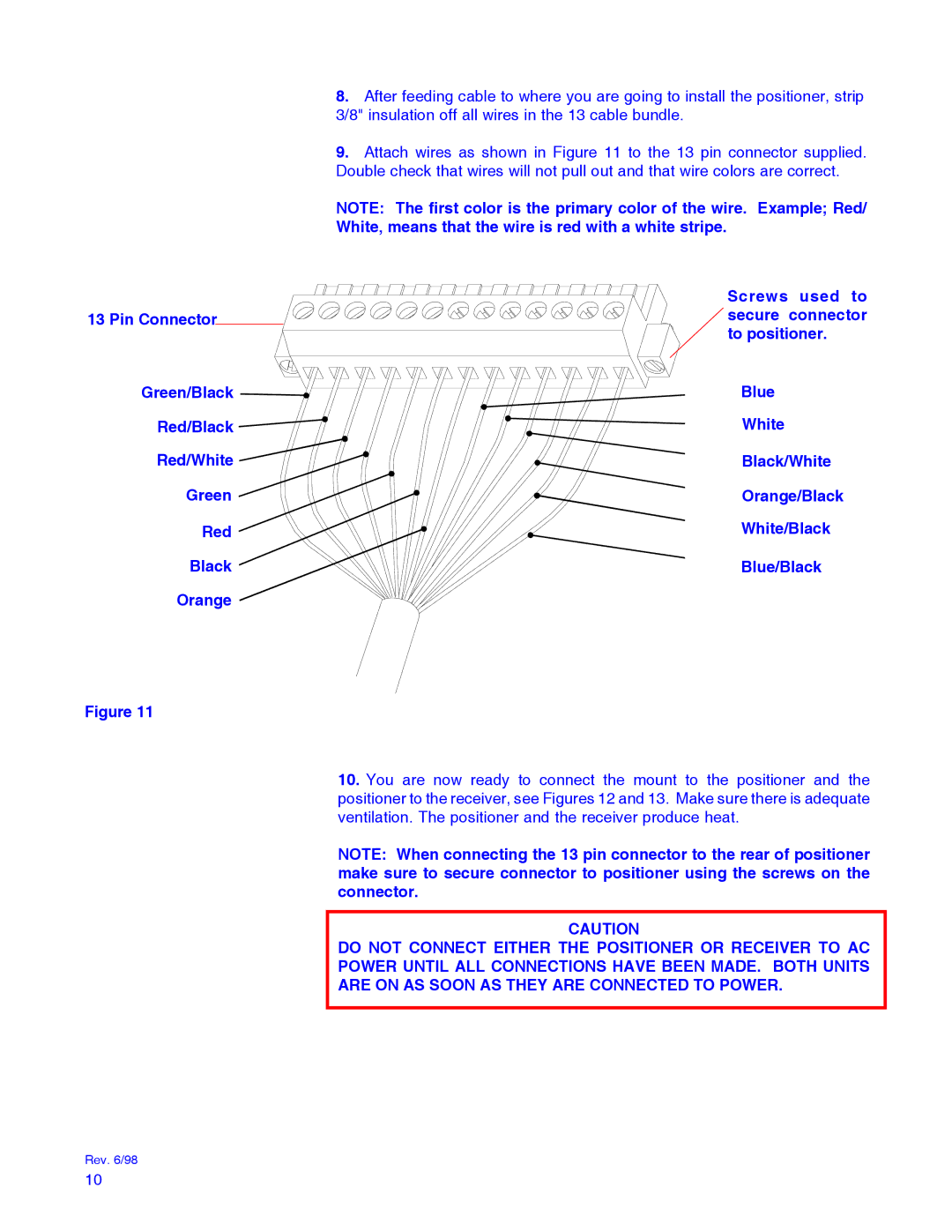
9.Attach wires as shown in Figure 11 to the 13 pin connector supplied. Double check that wires will not pull out and that wire colors are correct.
NOTE: The first color is the primary color of the wire. Example; Red/
White, means that the wire is red with a white stripe.
| Screws used to |
13 Pin Connector | secure connector |
| to positioner. |
Green/Black | Blue |
Red/Black | White |
Red/White | Black/White |
Green | Orange/Black |
Red | White/Black |
Black | Blue/Black |
Orange |
|
Figure 11
10.You are now ready to connect the mount to the positioner and the positioner to the receiver, see Figures 12 and 13. Make sure there is adequate ventilation. The positioner and the receiver produce heat.
NOTE: When connecting the 13 pin connector to the rear of positioner make sure to secure connector to positioner using the screws on the connector.
CAUTION
DO NOT CONNECT EITHER THE POSITIONER OR RECEIVER TO AC
POWER UNTIL ALL CONNECTIONS HAVE BEEN MADE. BOTH UNITS
ARE ON AS SOON AS THEY ARE CONNECTED TO POWER.
Rev. 6/98
10
