Input Operations
PORTID70
INPORT70
Register s0
Input and Output Ports
Applications with Few Input Sources
Readstrobe Interaction with FIFOs
Output Operations
Output Operations
Simple Output Structure for Few Output Destinations
Fpga Register
8Use Constant Directives to Declare Output Port Addresses
Pipelining for Maximum Performance
9Pipelining the Portid Decoding Improves Performance
Pipelining for Maximum Performance
Repartitioning the Design for Maximum Performance
Effective Pipelining Improves Read Performance
Instruction Storage Configurations
Standard Configuration Single 1Kx18 Block RAM
Instruction Storage Configurations
Two PicoBlaze Microcontrollers Share a 1Kx18 Code Image
6Using Distributed ROM for Instruction Memory
Distributed ROM Instead of Block RAM
Instruction Storage Configurations
Performance
Input Clock Frequency
Predicting Executing Performance
Frequency
Performance
PicoBlaze Development Tools
Assembler
PicoBlaze Development Tools
Assembly Errors
Input and Output Files
Configuring pBlazIDE for the PicoBlaze Microcontroller
Mediatronix pBlazIDE
Importing KCPSM3 Code into pBlazIDE
4Example of How Kcpsm Source Code Converts to pBlazIDE Code
Differences Between the KCPSM3 Assembler and pBlazIDE
Directives
Differences Between the KCPSM3 Assembler and pBlazIDE
Function KCPSM3 Directive PBlazIDE Directive
PicoBlaze Development Tools
KCPSM3 Module
Using the PicoBlaze Microcontroller in an Fpga Design
Vhdl Design Flow
Connecting the Program ROM
Using the PicoBlaze Microcontroller in an Fpga Design
Black Box Instantiation of KCPSM3 using KCPSM3.ngc
Generating the Program ROM using progrom.coe
Generating an ESC Schematic Symbol
Black Box Instantiation of KCPSM3 using KCPSM3.ngc
Using the PicoBlaze Microcontroller in an Fpga Design
Naming or Aliasing Registers
Assembler Directives
Locating Code at a Specific Address
Defining Constants
Naming the Program ROM Output File
Defining I/O Ports pBlazIDE
PBlazIDE
Defining I/O Ports pBlazIDE
Input Ports
Output Ports
Input/Output Ports
5Example of pBlazIDE Dsout Directive
Custom Instruction Op-Codes
Custom Instruction Op-Codes
Assembler Directives
Simulating PicoBlaze Code
Instruction Set Simulation with pBlazIDE
Simulator Control Buttons
Instruction Set Simulation with pBlazIDE
2pBlazIDE Simulator Control Buttons Function Assemble
Edit
Run
Step Over
Run to Cursor
Pause
Turbocharging Simulation using FPGAs
Turbocharging Simulation using FPGAs
Simulating PicoBlaze Code
Related Materials and References
Chapter Related Materials and References
Example Program Templates
KCPSM3 Syntax
PBlazIDE Syntax
Appendix Example Program Templates
PicoBlaze Instruction Set and Event Reference
ADD sX, Operand -Add Operand to Register sX
Addcy sX, Operand -Add Operand to Register sX with Carry
Appendix PicoBlaze Instruction Set and Event Reference
SX, Operand Logical Bitwise and Register sX with Operand
SX, Operand Logical Bitwise and Register sX with Operand
Examples
Condition
Table C-1CALL Instruction Conditions Description
Compare sX, Operand Compare Operand with Register sX
Figure C-4COMPARE Operation
Disable Interrupt Disable External Interrupt Input
Disable Interrupt Disable External Interrupt Input
Enable Interrupt Enable External Interrupt Input
Figure C-5FETCH Operation
KCPSM3 Instruction PBlazIDE Instruction
Portid Å Operand SX Å Inport PC Å PC +
Interrupt Event, When Enabled
Table C-2JUMP Instruction Conditions Description
Load sX, Operand Load Register sX with Operand
Or sX, Operand Logical Bitwise or Register sX with Operand
Or sX, Operand Logical Bitwise or Register sX with Operand
Figure C-7OUTPUT Operation and Fpga Interface Logic
Table C-3PicoBlaze Reset Values Resource Reset Event Effect
Reset Event
Reset Event
Table C-4RETURN Instruction Conditions Description
PBlazIDE Equivalent RET, RET C, RET NC, RET Z, RET NZ
RL sX Rotate Left Register sX
RR sX Rotate Right Register sX
Table C-5Rotate Left RL Operation
Table C-6Rotate Right RR Operation
Table C-7Shift Left Operations
SL 0 1 X a sX Shift Left Register sX
SL 0 1 X a sX Shift Left Register sX
SR 0 1 X a sX Shift Right Register sX
Shift Right with ‘ 0’ fill
Figure C-8STORE Operation
SUB sX, Operand -Subtract Operand from Register sX
Store sX, sY
Figure C-10SUBCY Instruction
Registers sX Flags CARRY, Zero PBlazIDE Equivalent Subc
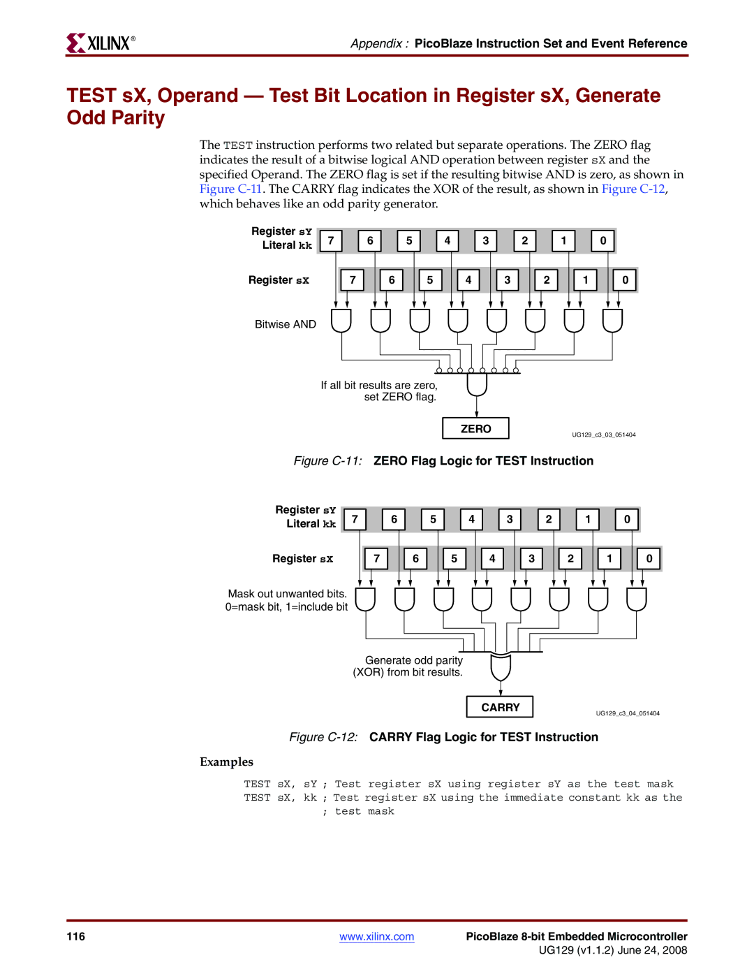
Figure C-11ZERO Flag Logic for Test Instruction
PicoBlaze 8-bit Embedded Microcontroller 117
XOR sX, Operand Logical Bitwise XOR Register sX with Operand
Instruction Codes
Table D-1PicoBlaze Instruction Codes
Jump Z
PicoBlaze 8-bit Embedded Microcontroller 121
Appendix Instruction Codes
Reg Description
Register and Scratchpad RAM Planning Worksheets
Registers
Loc Description
Scratchpad RAM
Appendix Register and Scratchpad RAM Planning Worksheets


 4

 3