R
Chapter 3: PicoBlaze Instruction Set
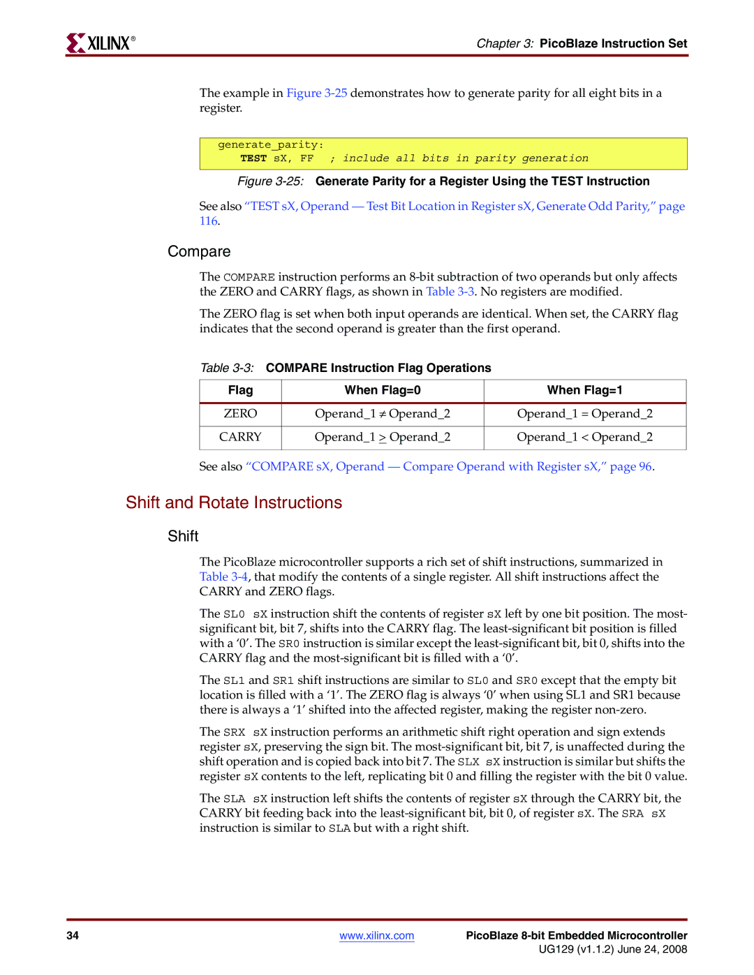
The example in Figure
generate_parity:
TEST sX, FF ; include all bits in parity generation
Figure 3-25: Generate Parity for a Register Using the TEST Instruction
See also “TEST sX, Operand — Test Bit Location in Register sX, Generate Odd Parity,” page 116.
Compare
The COMPARE instruction performs an
The ZERO flag is set when both input operands are identical. When set, the CARRY flag indicates that the second operand is greater than the first operand.
Table
Flag | When Flag=0 | When Flag=1 |
|
|
|
ZERO | Operand_1 ≠ Operand_2 | Operand_1 = Operand_2 |
|
|
|
CARRY | Operand_1 > Operand_2 | Operand_1 < Operand_2 |
|
|
|
See also “COMPARE sX, Operand — Compare Operand with Register sX,” page 96.
Shift and Rotate Instructions
Shift
The PicoBlaze microcontroller supports a rich set of shift instructions, summarized in
Table
CARRY and ZERO flags.
The SL0 sX instruction shift the contents of register sX left by one bit position. The most- significant bit, bit 7, shifts into the CARRY flag. The
The SL1 and SR1 shift instructions are similar to SL0 and SR0 except that the empty bit location is filled with a ‘1’. The ZERO flag is always ‘0’ when using SL1 and SR1 because there is always a ‘1’ shifted into the affected register, making the register
The SRX sX instruction performs an arithmetic shift right operation and sign extends register sX, preserving the sign bit. The
The SLA sX instruction left shifts the contents of register sX through the CARRY bit, the CARRY bit feeding back into the
34 | www.xilinx.com | PicoBlaze |
|
| UG129 (v1.1.2) June 24, 2008 |