Intel 82555 manual 3 100BASE-TX Transmit Framing, NRZ to MLT-3 Encoding Diagram

Page 19

Networking Silicon — 82555

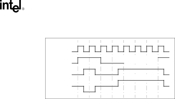
maintained (either positive, negative or zero). When an NRZ “1” arrives at the input of the encoder, the output steps to the next level. The order of steps is negative-zero-positive-zero which continues periodically. The figure below illustrates this process.

Clock

NRZ

NRZ1

MLT-3

1

1

1

1

1

1

0 0

00

0 0

1


0


0


1


0


0


1

0

0

1

1

1

Figure 6. NRZ to MLT-3 Encoding Diagram

4.2.3100BASE-TX Transmit Framing

The 82555 does not differentiate between the fields of the MAC frame containing preamble, start of frame delimiter, data and Cyclic Redundancy Check (CRC). When TXEN is asserted, the 82555 accepts data on the MII TXD[3:0] lines, encodes it, and sends it out onto the wire. The 82555 encodes the first byte of the preamble as the “JK” symbol, encodes all other pieces of data according to the 4B/5B lookup table, and adds the “TR” code after the end of the packet (de- assertion of TXEN). The 82555 scrambles and serializes the data into a 125 Mbps stream, encodes it as MLT-3, and drives it onto the wire. If TXERR is asserted during transmission of valid data, the 82555 transmits an invalid “H” symbol.

Datasheet

15

Image 19
Contents 82555 10/100 Mbps LAN Physical Layer Interface Product FeaturesRevision Description Networking SiliconContents Repeater Mode Functional Overview IntroductionCompliance to Industry Standards Networking Silicon Architectural Overview 100 Mbps ModeMII TX Interface 10 Mbps ModeMedia Independent Interface MII Repeater mode only Transmit Error From RICYes Pin Numbers and Labels Pin DefinitionsPin Types Clock PinsTwisted Pair Ethernet TPE Pins Media Independent Interface MII PinsMedia Access Control/Repeater Interface Control Pins External Bias Pins LED PinsMiscellaneous Control Pins VCC Power and Ground PinsVSS 100BASE-TX Transmit Blocks 100BASE-TX Adapter Mode OperationSymbol 5B Symbol Code 4B Nibble Code 100BASE-TX Transmit Clock GenerationInvalid 2 100BASE-TX Scrambler and MLT-3 Encoder3 100BASE-TX Transmit Framing NRZ to MLT-3 Encoding DiagramTransmit Driver 100BASE-TX Receive BlocksVendor Model/Type 100BASE-TX Collision Detection Auto-Negotiation 100BASE-TX Link Integrity and Auto-Negotiation SolutionCombination Tx/T4 Auto-Negotiation Solution Link IntegrityAuto 10/100 Mbps Speed Selection Adapter Mode AddressesNetworking Silicon Datasheet 10BASE-T Receive Blocks 10BASE-T Functionality in Adapter Mode10BASE-T Transmit Clock Generation 10BASE-T Transmit Blocks10BASE-T Jabber Control Function 3 10BASE-T Error Detection and Reporting10BASE-T Collision Detection 10BASE-T Link Integrity10BASE-T Full Duplex Networking Silicon Datasheet Special Repeater Features Repeater ModeConnectivity Clock Signal Example MDI Frame Structure Management Data InterfaceTransition Bits Name Description DefaultMDI Registers MDI Registers 010BASE-T Register 1 Status Register Bit DefinitionsRegister 2 82555 Identifier Register Bit Definitions MDI Registers 16 MDI Registers 8100BASE-TX Register 17 82555 Special Control Bit Definitions150 Actled Liled Register 22 Receive Symbol Error Counter Bit DefinitionsPriority Technology Bit Setting TechnologyAuto-Negotiation Functionality DescriptionPriority Parallel Detect and Auto-NegotiationAuto-Negotiation and Parallel Detect Networking Silicon Datasheet LED Descriptions Networking Silicon Datasheet Scrambler Bypass Reset and Miscellaneous Test ModesReset LoopbackNumber Code Test Instruction Select Input to Tout Test Instruction CodingGeneral Operating Conditions Electrical Specifications and Timing ParametersDC Characteristics Absolute Maximum RatingsTotal supply current 230 Leakage on analog pins 11.3.3 100BASE-TX Voltage/Current DC CharacteristicsMII Clock Specifications AC CharacteristicsSymbol Parameter Conditions Min Typ Max Units MII Clocks AC Timing MII Timing ParametersRXC tri-stated a Repeater Mode Timing ParametersSquelch Test Timing Parameters Transmit Packet Timing ParametersReceive Packet Timing Parameters Jabber Timing ParametersAuto-Negotiation Fast Link Pulse FLP Timing Parameters 11.4.8 10BASE-T Normal Link Pulse NLP Timing Parameters11.4.11 X1 Clock Specifications Reset Timing ParametersX1 Clock Specifications 11.4.12 100BASE-TX Transmitter AC Specification12.0 82555 Package Information Symbol Description Min Norm Max10.0