Omron CPM1A operation manual Three-word Monitor

Page 105
c200
89AB

Programming Console Operations

Section 4-3


(Word monitor)

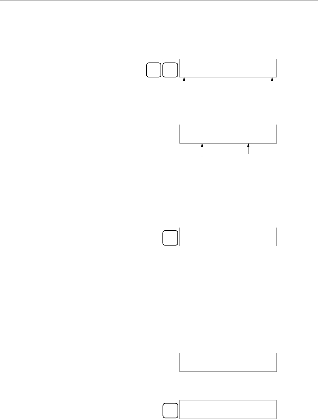
2.Press the SHIFT and then the MONTR Key to begin binary monitoring. The ON/OFF status of the selected word’s 16 bits will be shown along the bottom of the display. A 1 indicates a bit is on, and a 0 indicates it is off.

SHIFT MONTR

c010 MONTR

0000000000000000

Bit 15

Bit 00

The status of force-set bits is indicated by “S,” and the status of a force-reset bits is indicated by “R,” as shown below.

c010 MONTR 000S0000000R0000

Force-set bit

Force-reset bit

Note a) The status of displayed bits can be changed at this point. Refer to 4-3-20 Binary Data Modification for details.

b)The Up or Down Arrow Key can be pressed to display the status of the previous or next word’s bits.

3.Press the CLR Key to end binary monitoring and return to the normal moni- toring display.

CLR

c010

0000

4-3-14 Three-word Monitor

This operation is used to monitor the status of three consecutive words. It is possible in any mode.

RUN

MONITOR

PROGRAM


OK

OK

OK

1, 2, 3... 1. Monitor the status of the first of the three words according to the procedure described in 4-3-11 Bit, Digit, Word Monitor.

If 2 or more words are being monitored, the desired first word should be left- most on the display.

(Word monitor)

2.Press the EXT Key to begin 3-word monitoring. The status of the selected word and the next two words will be displayed, as shown below. In this case, DM 0000 was selected.

EXT

c202 c201 c200

0123 4567 89AB

The Up and Down Arrow Keys can be used to shift one address up or down.

The status of the displayed words can be changed at this point. Refer to 4-3-17Three-word Data Modification.

The display can be changed to display ASCII text, which is useful when three consecutive words containing an ASCII message are displayed. Refer to 4-3-25Hex-ASCII Display Change.

93

Image 105
Contents CPM1A CPM1A Programmable Controllers  Omron Omron Product ReferencesTable of Contents Appendices About this Manual Precautions General Precautions Safety PrecautionsIntended Audience Application Precautions Operating Environment PrecautionsXiv Application Precautions Backup method Data Applicable Directives EC DirectivesConcepts Conformance to EC DirectivesXviii Section CPM1A Features and Functions 1 CPM1A FeaturesSection NT Link Communications CompoBus/S I/O Link Units Using the PTStandard Peripheral Devices Programming is PossibleCPU Units 2 I/O Terminal and IR Bit AllocationExpansion I/O Units Unit Relay output Transistor output Sink type Source typeControl Corresponding IR word Setting range BCD 3 CPM1A FunctionsSet value Word Word 001 or later PC model Input bits Response time PC model Input bits Min. input pulse width Mode FunctionPulse output single-phase output CompoBus/S Slave Functions CPM1A-SRT21 Temperature Sensor Unit FunctionsCPU Unit and Expansion I/O Unit Configuration System ConfigurationCPU Unit and Expansion Unit CPM1A CPU UnitsUnit Max. number Inputs Outputs Model Units Expansion I/O UnitsExpansion Units Host Link CommunicationsProgrammable Terminal Connecting to aOne-to-one PC Link Communications Adapters and CablesName Usage Model number One-to-one NT Link Communications Name SpecificationsCompoBus/S I/O Link Connections Peripheral Device ConnectionsName Model number Sysmac Support Software SYSMAC-CPT SupportPrevious specifications New specifications Relevant pages Revised SpecificationsUnit Specifications and Components Specifications General SpecificationsCPM1A-10CDR-j CPM1A-20CDR-j CPM1A-30CDR-j CPM1A-40CDR-j Characteristics Memory Backup CPU Unit Input Specifications 3 I/O SpecificationsIncrement Mode 5 kHz Max SpecificationExpansion I/O Unit Input Specifications Relay Output CPU Unit and Expansion I/O Unit Output SpecificationsTransistor Output Source Type Transistor Output Sink Type20EDT 8ET 10CDT1-D 20CDT1-D 30CDT1-D 40CDT1-D 20EDT1 8ET1Communications Adapter Specifications RS-232C Adapter SpecificationsRS-422 Adapter Specifications CPU Unit Components Unit ComponentsCPM1A-10CDR-j/10CDT-D/10CDT1-D 10 I/O Terminals CPM1A-40CDR-j/40CDT-D/40CDT1-D 40 I/O TerminalsIndicator Status Meaning Fatal error Input indicatorsCPU Unit Component Descriptions Expansion I/O Unit with 20 I/O Terminals Expansion I/O Unit ComponentsExpansion I/O Unit with 8 Input Terminals Expansion I/O Unit with 8 Output TerminalsAnalog I/O Unit Components Temperature Sensor Unit ComponentsCPM1A-TS101/102 CPM1A-TS001/002Set value Thermocouple Range C Range F Set value Platinum resistance Range C Range FCompoBus/S I/O Link Unit Components Pins FunctionCommunications Adapter Components RS-232C AdapterRS-422 Adapter Installation and Wiring Power Supply Wiring Design PrecautionsPower Supply Voltage 4 CPM1A Power InterruptionsInstallation Site Conditions Selecting an Installation SiteMomentary Power Failure Detection Automatic RestartOverheating Panel/Cabinet Installation2 CPM1A Installation Installing the CPM1A1 CPM1A Orientation CorrectDIN Track Installation Connecting an Expansion I/O Unit InstallationRemoval Section General Precautions for Wiring Wiring and ConnectionsLine Noise Hanging DuctsFloor Ducts Ground WiringConduits GroundingTo 240-VAC Power Supply Crimp ConnectorsVDC Power Supply Input Configuration Input WiringCPM1A-8ED Outputs Input Wiring ExampleInput Devices Device Circuit diagramInductive Loads Relay Output Wiring Output WiringOutput Configurations CPM1A-8ER Transistor Output Wiring Sink Type CPM1A-8ET CPM1A-40CDT1-D Transistor Output Wiring Source TypeOutput Short Protection Polarity of Power Supply for the LoadFuse Insertion Inrush Current ConsiderationsPeripheral Device Connection Host Link ConnectionsOne-to-one Host Link Connection One-to-N Host Link Connection RDB SDB RDA SDA One-to-one PC Link Connections One-to-one NT Link Connections C200HX/HG/HE PC Using Peripheral Devices SSS System Setup 2 CPM1A Restrictions and PrecautionsSupport Software Capabilities Online Editing Offline OperationsCopy Group Name Description Go ToFill PrintPC Setup File Time ChartGroup Name Description Utility Data Area Lists ChangeOnline Operations Offline and Online Operations Compatible Programming Consoles Using a Programming ConsoleCQM1-PRO01-E C200H-PRO27-EBuzzer Volume Mode SwitchDifferent Keys Contrast ControlProgram Mode Changing the CPM1A’s Mode with the Mode SwitchMonitor Mode RUN ModePanel Installation Connecting the Programming ConsolePreparation for Operation Entering the PasswordProgram Password Program BZ Overview Programming Console OperationsClearing Memory All ClearPartial Clear Reading/Clearing Error Messages Buzzer OperationKey Sequence OFF Entering or Editing Programs Writing a Word Address Writing Hexadecimal, BCD ConstantWriting an Unsigned Decimal Number #FFF6Writing a Word Address DM Bit Operand Search Instruction SearchInsertion Inserting and Deleting Instructions00207INSERT END Not DeletionDelete END Checking the Program00178CIRCUIT ERR Corrected Program Bit Monitor 11 Bit, Digit, Word Monitor Cont Word MonitorMultiple Address Monitoring Channel LRCLR Channel LR Binary Monitor Differentiation Monitor@OFF OFF OFF CLR OFF OFF OFFThree-word Monitor Unsigned Decimal Monitor Signed Decimal MonitorChanging Timer, Counter SV Three-word Data Modification3CH CHG? Hexadecimal, BCD Data Modification Inputting a New SV ConstantIncrementing and Decrementing a Constant Binary Data Modification Pres VAL?Montr D0000 Montr Signed Decimal Data ModificationUnsigned Decimal Data Modification Force Set, ResetHex-ASCII Display Change Clear Force Set/ResetOn on 00000FORCE RELE?Programming Example Program PasswordDisplaying the Cycle Time Preparatory Operations00000MEMORY CLR? HR CNT DM Montr END HR CNT DM Example Program Programming ProceduresInputting the One-second Timer Programming ProceduresInputting the Self-holding Bit Write NOPInputting the 10-count Counter Inputting the Two-second TimerLD not Inputting the Flicker OutputInputting the END001 Instruction Monitor BZ Test Run in Monitor ModeTest Runs and Error Processing 2 CPM1A Test Run Procedure Initial System Checks and Test Run ProcedureInitial System Checks Points to checkFlash Memory Precautions CPM1A Cycle ErrorFatal Errors Non-fatal ErrorsSelf-diagnosis Functions Message FAL No Meaning and appropriate responseUser-defined Errors Identifying ErrorsError Messages Error FlagsProgramming Errors Programming Console Operation ErrorsFALS07 Message MSG46Circuit ERR Type Message Meaning and appropriate responseMain Check Troubleshooting FlowchartsPower Supply Check Follow the Memory Error Fatal Error CheckNon-fatal Error Check 121 122 Environmental Conditions Check Memory Error Check Power supply Allowable voltage fluctuation range Maintenance InspectionsInspection Items Inspection items Details Criteria RemarksNecessary Tools for Inspection Handling PrecautionsStandard Tools Measurement DevicesExpansion Memory Unit Overview PrecautionsMemory Areas ButtonSpecifications and Nomenclature SpecificationsNomenclature Handling LED IndicatorMounting/Removing Eeprom Mounting EepromPC Connections Peripheral Port Communications SettingsCPM1, CPM1A, CPM2A CQM1, and SRM1 PCsUploading Programs DisconnectingDownloading Programs Operation Procedure134 135 Expansion Units Standard ModelsCPU Units Expansion I/O UnitsDescription Specifications Model number Temperature Sensor UnitsCompoBus/S I/O Link Unit Communications AdaptersPeripheral Devices Name Appearance Model Number SpecificationsCPM1A-10CDR-j/10CDT-D/10CDT1-D CPU Unit DimensionsCPM1A-20CDR-j/20CDT-D/20CDT1-D CPU Unit CPM1A-30CDR-j/30CDT-D/30CDT1-D CPU UnitCPM1A-40CDR-j/40CDT-D/40CDT1-D CPU Unit CPM1A-20EDjExpansion I/O UnitCPM1A-8jjjExpansion I/O Unit CPM1A-TSjjjTemperature Sensor Unit CPM1A-MAD01 Analog I/O UnitCPM1A-SRT21 CompoBus/S I/O Link Unit CPM1-CIF11 RS-422 Adapter CPM1-CIF01 RS-232C AdapterAppendix B Dimensions with Peripheral Devices AttachedAscii ACPAUTOEXEC.BAT BCDBit number Bit designatorBit-control instruction BlockCTS CONFIG.SYSDIP switch DefaultData link Data link areaEprom EepromFCS Initialization error DelayInput signal InstallLED JISLSS OFF NotPCB Prom RAMRAS SCP ROMSSS System configuration Syntax errorSystem error System error messageWDT Numbers Index 165 166 167 Revision History Revision code Date Revised content
Related manuals
Manual 6 pages 62.26 Kb