Programming Console Operations | Section | |
|
|
|
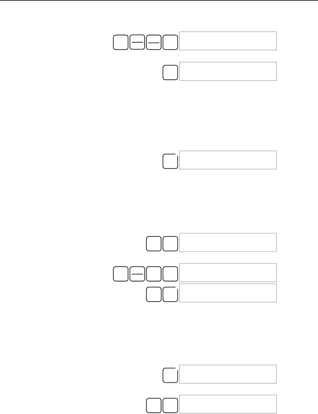
Multiple Address Monitoring
2. Input the word address of the desired word.
| CH | *EM | B | 00000 |
| |
SHIFT | 1 CHANNEL LR | 01 | ||||
| LR |
| ||||
| *DM |
|
3. Press the MONTR Key to begin monitoring.
cL01
MONTR FFFF
The Up or Down Arrow Key can be pressed to display the status of the pre- vious or next word.
The displayed word’s status can be changed using the Hexadecimal/BCD Data Modification operation. Refer to Refer to
4. Press the CLR Key to end monitoring.
![]() 00000
00000
CLR CHANNEL LR 01
Note The operating mode can be changed without altering the current monitor display by holding down the SHIFT Key and then changing the operating mode.
The status of up to six bits and words can be monitored simultaneously, although only three can be shown on the display at any one time.
1, 2, 3... 1. Press the CLR Key to bring up the initial display.
2. Input the address of the first bit or word and press the MONTR Key.
T000
TIM MONTR 0100
3. Repeat step 2 up to 6 times to display the next addresses to be monitored.
| CONT | B |
| 00001 | T000 |
SHIFT | MONTR |
|
| ||
# | 1 | ^ OFF 0100 | |||
|
|
|
|
| |
![]() D000000001 T000
D000000001 T000
DM MONTR 0000^ OFF 0100
If 4 or more bits and words are being monitored, the bits and words that do not appear on the display can be displayed by pressing the MONTR Key. If the MONTR Key is pressed alone, the display will shift to the right.
If more than six bits and/or words are input, monitoring of the bit or word input first will be canceled.
4.Press the CLR Key to stop monitoring the leftmost bit or word and clear it from the display.
![]() 00001 T000
00001 T000
CLR ^ OFF 0100
5. Press the SHIFT and CLR Keys to end monitoring altogether.
00000 |
|
SHIFT CLR CONT | 00001 |
Note Press the SHIFT Key, CLR Key, and then CLR Key again to return to the initial Programming Console display with the multiple address monitoring state unchanged. Press the SHIFT Key and then the MONTR Key from the initial dis- play to return to the multiple address monitoring state. The monitoring states can be retained for 6 bits and words.
The operating mode can be changed without altering the current monitor display by holding down the SHIFT Key and then changing the operating mode.
91