Omron CPM1A operation manual Test Run in Monitor Mode, Monitor BZ

Page 119

Programming Example

Section 4-4


4-4-4 Checking the Program

Check the program syntax in PROGRAM mode to make sure that the program has been input correctly.

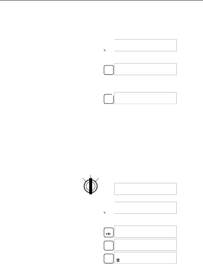
1, 2, 3... 1. Press the CLR Key to bring up the initial display.

00000

CLR

2.Press the SRCH Key. An input prompt will appear requesting the desired check level.

SRCH

00000PROG CHK CHK LBL (0)2)?

3.Input the desired check level (0, 1, or 2). The program check will begin when the check level is input, and the first error found will be displayed. If no errors are found, the following display will appear.

A 00017PROG CHK

0 END (001)00.1KW

Note Refer to 5-5 Programming Errors for details on check levels and the programming errors that may be displayed during a program check.

4.Press the SRCH Key to continue the search. The next error will be dis- played. Continue pressing the SRCH Key to continue the search.

The search will continue until an END(01) instruction or the end of Program Memory is reached.

If errors are displayed, edit the program to correct the errors and check the pro- gram again. Continue checking the program until all errors have been corrected.

4-4-5 Test Run in MONITOR Mode

Switch the CPM1A in MONITOR mode and check the operation of the program.

1, 2, 3... 1. Set the Programming Console’s mode switch to MONITOR mode.

MONITOR

RUN PROGRAM

<MONITOR> BZ

2. Press the CLR Key to bring up the initial display.

00000

CLR

3.Force-set the start input bit (IR 00000) from the Programming Console to start the program.

LD

00000


LD

00000


00000


MONTR

^ OFF


00000


SET

ON


The cursor in the lower left corner of the display indicates that the force set is in progress. The bit will remain ON as long as the Set Key is held down.

4.The output indicator for output IR 01000 will flash ten times if the program is operating correctly. The indicator should go OFF after ten one-second flashes.

There is a mistake in the program if the output indicator doesn’t flash. In this case, check the program and force set/reset bits to check operation.

107

Image 119
Contents CPM1A CPM1A Programmable Controllers  Omron Omron Product ReferencesTable of Contents Appendices About this Manual Precautions Intended Audience General PrecautionsSafety Precautions Application Precautions Operating Environment PrecautionsXiv Application Precautions Backup method Data Conformance to EC Directives EC DirectivesApplicable Directives ConceptsXviii Section Section CPM1A Features and Functions1 CPM1A Features Programming is Possible Using the PTNT Link Communications CompoBus/S I/O Link Units Standard Peripheral DevicesUnit Relay output Transistor output Sink type Source type 2 I/O Terminal and IR Bit AllocationCPU Units Expansion I/O UnitsSet value Word Word 001 or later Control Corresponding IR word Setting range BCD3 CPM1A Functions PC model Input bits Response time PC model Input bits Min. input pulse width Mode FunctionPulse output single-phase output CompoBus/S Slave Functions CPM1A-SRT21 Temperature Sensor Unit FunctionsCPM1A CPU Units System ConfigurationCPU Unit and Expansion I/O Unit Configuration CPU Unit and Expansion UnitUnit Max. number Inputs Outputs Model Units Expansion I/O UnitsExpansion Units Host Link CommunicationsProgrammable Terminal Connecting to aName Usage Model number One-to-one PC Link CommunicationsAdapters and Cables Peripheral Device Connections Name SpecificationsOne-to-one NT Link Communications CompoBus/S I/O Link ConnectionsName Model number Sysmac Support Software SYSMAC-CPT SupportPrevious specifications New specifications Relevant pages Revised SpecificationsUnit Specifications and Components CPM1A-10CDR-j CPM1A-20CDR-j CPM1A-30CDR-j CPM1A-40CDR-j SpecificationsGeneral Specifications Characteristics Memory Backup Specification 3 I/O SpecificationsCPU Unit Input Specifications Increment Mode 5 kHz MaxExpansion I/O Unit Input Specifications Relay Output CPU Unit and Expansion I/O Unit Output Specifications10CDT1-D 20CDT1-D 30CDT1-D 40CDT1-D 20EDT1 8ET1 Transistor Output Sink TypeTransistor Output Source Type 20EDT 8ETRS-422 Adapter Specifications Communications Adapter SpecificationsRS-232C Adapter Specifications CPM1A-40CDR-j/40CDT-D/40CDT1-D 40 I/O Terminals Unit ComponentsCPU Unit Components CPM1A-10CDR-j/10CDT-D/10CDT1-D 10 I/O TerminalsCPU Unit Component Descriptions Indicator Status MeaningFatal error Input indicators Expansion I/O Unit with 8 Output Terminals Expansion I/O Unit ComponentsExpansion I/O Unit with 20 I/O Terminals Expansion I/O Unit with 8 Input TerminalsAnalog I/O Unit Components Temperature Sensor Unit ComponentsSet value Platinum resistance Range C Range F CPM1A-TS001/002CPM1A-TS101/102 Set value Thermocouple Range C Range FCompoBus/S I/O Link Unit Components Pins FunctionRS-422 Adapter Communications Adapter ComponentsRS-232C Adapter Installation and Wiring 4 CPM1A Power Interruptions Design PrecautionsPower Supply Wiring Power Supply VoltageAutomatic Restart Selecting an Installation SiteInstallation Site Conditions Momentary Power Failure DetectionOverheating Panel/Cabinet InstallationCorrect Installing the CPM1A2 CPM1A Installation 1 CPM1A OrientationDIN Track Installation Removal Connecting an Expansion I/O UnitInstallation Section Hanging Ducts Wiring and ConnectionsGeneral Precautions for Wiring Line NoiseGrounding Ground WiringFloor Ducts ConduitsTo 240-VAC Power Supply Crimp ConnectorsVDC Power Supply Input Configuration Input WiringCPM1A-8ED Outputs Input Wiring ExampleInput Devices Device Circuit diagramInductive Loads Relay Output Wiring Output WiringOutput Configurations CPM1A-8ER Transistor Output Wiring Sink Type CPM1A-8ET CPM1A-40CDT1-D Transistor Output Wiring Source TypeOutput Short Protection Polarity of Power Supply for the LoadFuse Insertion Inrush Current ConsiderationsOne-to-one Host Link Connection Peripheral Device ConnectionHost Link Connections One-to-N Host Link Connection RDB SDB RDA SDA One-to-one PC Link Connections One-to-one NT Link Connections C200HX/HG/HE PC Using Peripheral Devices Support Software Capabilities SSS System Setup2 CPM1A Restrictions and Precautions Online Editing Offline OperationsPrint Group Name Description Go ToCopy FillChange File Time ChartPC Setup Group Name Description Utility Data Area ListsOnline Operations Offline and Online Operations C200H-PRO27-E Using a Programming ConsoleCompatible Programming Consoles CQM1-PRO01-EContrast Control Mode SwitchBuzzer Volume Different KeysRUN Mode Changing the CPM1A’s Mode with the Mode SwitchProgram Mode Monitor ModePanel Installation Connecting the Programming ConsolePreparation for Operation Entering the PasswordProgram Password Program BZ Overview Programming Console OperationsPartial Clear Clearing MemoryAll Clear Key Sequence Reading/Clearing Error MessagesBuzzer Operation OFF Entering or Editing Programs Writing a Word Address Writing Hexadecimal, BCD ConstantWriting a Word Address DM Writing an Unsigned Decimal Number#FFF6 Bit Operand Search Instruction SearchDeletion Inserting and Deleting InstructionsInsertion 00207INSERT END NotCorrected Program Checking the ProgramDelete END 00178CIRCUIT ERRWord Monitor 11 Bit, Digit, Word MonitorBit Monitor ContCLR Channel LR Multiple Address MonitoringChannel LR CLR OFF OFF OFF Differentiation MonitorBinary Monitor @OFF OFF OFFThree-word Monitor Unsigned Decimal Monitor Signed Decimal Monitor3CH CHG? Changing Timer, Counter SVThree-word Data Modification Incrementing and Decrementing a Constant Hexadecimal, BCD Data ModificationInputting a New SV Constant Montr Binary Data ModificationPres VAL? D0000 Montr Signed Decimal Data ModificationUnsigned Decimal Data Modification Force Set, Reset00000FORCE RELE? Clear Force Set/ResetHex-ASCII Display Change On onPreparatory Operations Program PasswordProgramming Example Displaying the Cycle Time00000MEMORY CLR? HR CNT DM Montr END HR CNT DM Example Program Programming Procedures Write NOP Programming Procedures Inputting the One-second Timer Inputting the Self-holding BitInputting the 10-count Counter Inputting the Two-second TimerInputting the END001 Instruction LD notInputting the Flicker Output Monitor BZ Test Run in Monitor ModeTest Runs and Error Processing Points to check Initial System Checks and Test Run Procedure2 CPM1A Test Run Procedure Initial System ChecksFlash Memory Precautions CPM1A Cycle ErrorMessage FAL No Meaning and appropriate response Non-fatal ErrorsFatal Errors Self-diagnosis FunctionsError Flags Identifying ErrorsUser-defined Errors Error MessagesMessage MSG46 Programming Console Operation ErrorsProgramming Errors FALS07Circuit ERR Type Message Meaning and appropriate responseMain Check Troubleshooting FlowchartsPower Supply Check Follow the Memory Error Fatal Error CheckNon-fatal Error Check 121 122 Environmental Conditions Check Memory Error Check Inspection items Details Criteria Remarks Maintenance InspectionsPower supply Allowable voltage fluctuation range Inspection ItemsMeasurement Devices Handling PrecautionsNecessary Tools for Inspection Standard ToolsExpansion Memory Unit Button PrecautionsOverview Memory AreasNomenclature Specifications and NomenclatureSpecifications Mounting Eeprom LED IndicatorHandling Mounting/Removing EepromCQM1, and SRM1 PCs Peripheral Port Communications SettingsPC Connections CPM1, CPM1A, CPM2AUploading Programs DisconnectingDownloading Programs Operation Procedure134 135 Expansion I/O Units Standard ModelsExpansion Units CPU UnitsCommunications Adapters Temperature Sensor UnitsDescription Specifications Model number CompoBus/S I/O Link UnitPeripheral Devices Name Appearance Model Number SpecificationsCPM1A-30CDR-j/30CDT-D/30CDT1-D CPU Unit DimensionsCPM1A-10CDR-j/10CDT-D/10CDT1-D CPU Unit CPM1A-20CDR-j/20CDT-D/20CDT1-D CPU UnitCPM1A-8jjjExpansion I/O Unit CPM1A-40CDR-j/40CDT-D/40CDT1-D CPU UnitCPM1A-20EDjExpansion I/O Unit CPM1A-SRT21 CompoBus/S I/O Link Unit CPM1A-TSjjjTemperature Sensor UnitCPM1A-MAD01 Analog I/O Unit CPM1-CIF11 RS-422 Adapter CPM1-CIF01 RS-232C AdapterAppendix B Dimensions with Peripheral Devices AttachedBCD ACPAscii AUTOEXEC.BATBlock Bit designatorBit number Bit-control instructionCTS CONFIG.SYSData link area DefaultDIP switch Data linkEprom EepromFCS Install DelayInitialization error Input signalLED JISLSS OFF NotPCB RAS PromRAM SCP ROMSSS System error message Syntax errorSystem configuration System errorWDT Numbers Index 165 166 167 Revision History Revision code Date Revised content
Related manuals
Manual 6 pages 62.26 Kb