Omron CPM1A Inserting and Deleting Instructions, Insertion, 00207INSERT END Not, Deletion

Page 100

Programming Console Operations

Section 4-3


5. The search will continue until an END instruction or the end of Program Memory is reached. In this case, an END instruction was reached.

Indicates the address of END instruction.

SRCH

00397CONT SRCH END (001)00.4KW

Indicates the amount used by the user program in units of 0.1 Kwords.

4-3-9 Inserting and Deleting Instructions

This operation is used to insert or delete instructions from the program. It is pos- sible in PROGRAM mode only.

RUN

MONITOR

PROGRAM


No

No

OK

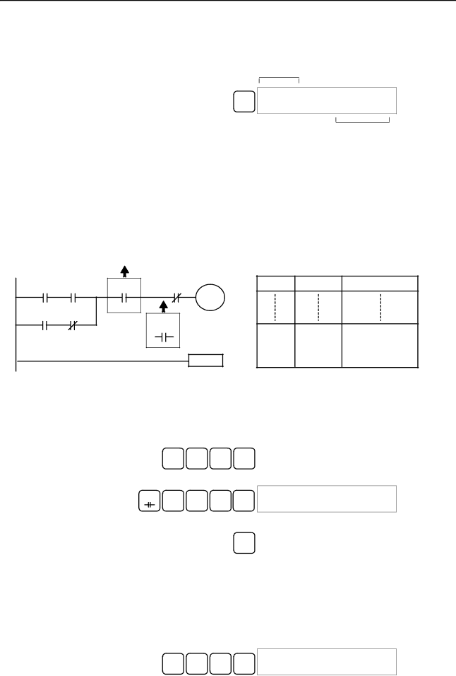
To demonstrate this operation, an IR 00105 NO condition will be inserted at program address 00206 and an IR 00103 NO condition deleted from address 00205, as shown in the following diagram.

Original Program

00100 00101

00201 00102

00103

Delete

00104

00105

Insert

01000

END(01)

Delete

Address Instruction

Operands

00205

AND

00103

00206

AND NOT

00104

00207

OUT

01000

00208

END(01)

-

Insert

Insertion

Follow the procedure below to insert the IR 00105 NO condition at address


00206.


1, 2, 3...

1.

Press the CLR Key to bring up the initial display.


2.

Input the address where the NO condition will be inserted and press the


Down Arrow Key. It is not necessary to input leading zeroes.


C

A

6

00206READ


2

0

AND NOT

00104


3. Input the new instruction and press the INS Key.

AND

B

A

F


00206INSERT?


1

0

5

INS

AND

00105

4. Press the Down Arrow Key to insert the new instruction.


00207INSERT END


AND NOT

00104


Note For instructions that require more operands (such as set values),


input the operands and then press the WRITE Key.

Deletion

Follow the procedure below to delete the IR 00103 NO condition at address


00205.


1, 2, 3... 1. Press the CLR Key to bring up the initial display.

2.Input the address where the NO condition will be deleted and press the Down Arrow Key. It is not necessary to input leading zeroes.

C

A

F

00205READ


2

0

5

AND

00103


88

Image 100
Contents CPM1A CPM1A Programmable Controllers Omron Product References  OmronTable of Contents Appendices About this Manual Precautions Safety Precautions General PrecautionsIntended Audience Operating Environment Precautions Application PrecautionsXiv Application Precautions Backup method Data EC Directives Applicable DirectivesConcepts Conformance to EC DirectivesXviii Section 1 CPM1A Features CPM1A Features and FunctionsSection Using the PT NT Link Communications CompoBus/S I/O Link UnitsStandard Peripheral Devices Programming is Possible2 I/O Terminal and IR Bit Allocation CPU UnitsExpansion I/O Units Unit Relay output Transistor output Sink type Source type3 CPM1A Functions Control Corresponding IR word Setting range BCDSet value Word Word 001 or later PC model Input bits Response time Mode Function PC model Input bits Min. input pulse widthPulse output single-phase output Temperature Sensor Unit Functions CompoBus/S Slave Functions CPM1A-SRT21System Configuration CPU Unit and Expansion I/O Unit ConfigurationCPU Unit and Expansion Unit CPM1A CPU UnitsExpansion I/O Units Unit Max. number Inputs Outputs Model UnitsHost Link Communications Expansion UnitsConnecting to a Programmable TerminalAdapters and Cables One-to-one PC Link CommunicationsName Usage Model number Name Specifications One-to-one NT Link CommunicationsCompoBus/S I/O Link Connections Peripheral Device ConnectionsSysmac Support Software SYSMAC-CPT Support Name Model numberRevised Specifications Previous specifications New specifications Relevant pagesUnit Specifications and Components General Specifications SpecificationsCPM1A-10CDR-j CPM1A-20CDR-j CPM1A-30CDR-j CPM1A-40CDR-j Characteristics Memory Backup 3 I/O Specifications CPU Unit Input SpecificationsIncrement Mode 5 kHz Max SpecificationExpansion I/O Unit Input Specifications CPU Unit and Expansion I/O Unit Output Specifications Relay OutputTransistor Output Sink Type Transistor Output Source Type20EDT 8ET 10CDT1-D 20CDT1-D 30CDT1-D 40CDT1-D 20EDT1 8ET1RS-232C Adapter Specifications Communications Adapter SpecificationsRS-422 Adapter Specifications Unit Components CPU Unit ComponentsCPM1A-10CDR-j/10CDT-D/10CDT1-D 10 I/O Terminals CPM1A-40CDR-j/40CDT-D/40CDT1-D 40 I/O TerminalsFatal error Input indicators Indicator Status MeaningCPU Unit Component Descriptions Expansion I/O Unit Components Expansion I/O Unit with 20 I/O TerminalsExpansion I/O Unit with 8 Input Terminals Expansion I/O Unit with 8 Output TerminalsTemperature Sensor Unit Components Analog I/O Unit ComponentsCPM1A-TS001/002 CPM1A-TS101/102Set value Thermocouple Range C Range F Set value Platinum resistance Range C Range FPins Function CompoBus/S I/O Link Unit ComponentsRS-232C Adapter Communications Adapter ComponentsRS-422 Adapter Installation and Wiring Design Precautions Power Supply WiringPower Supply Voltage 4 CPM1A Power InterruptionsSelecting an Installation Site Installation Site ConditionsMomentary Power Failure Detection Automatic RestartPanel/Cabinet Installation OverheatingInstalling the CPM1A 2 CPM1A Installation1 CPM1A Orientation CorrectDIN Track Installation Installation Connecting an Expansion I/O UnitRemoval Section Wiring and Connections General Precautions for WiringLine Noise Hanging DuctsGround Wiring Floor DuctsConduits GroundingCrimp Connectors To 240-VAC Power SupplyVDC Power Supply Input Wiring Input ConfigurationCPM1A-8ED Input Wiring Example OutputsDevice Circuit diagram Input DevicesInductive Loads Output Wiring Relay Output WiringOutput Configurations CPM1A-8ER Transistor Output Wiring Sink Type CPM1A-8ET Transistor Output Wiring Source Type CPM1A-40CDT1-DPolarity of Power Supply for the Load Output Short ProtectionInrush Current Considerations Fuse InsertionHost Link Connections Peripheral Device ConnectionOne-to-one Host Link Connection One-to-N Host Link Connection RDB SDB RDA SDA One-to-one PC Link Connections One-to-one NT Link Connections C200HX/HG/HE PC Using Peripheral Devices 2 CPM1A Restrictions and Precautions SSS System SetupSupport Software Capabilities Offline Operations Online EditingGroup Name Description Go To CopyFill PrintFile Time Chart PC SetupGroup Name Description Utility Data Area Lists ChangeOnline Operations Offline and Online Operations Using a Programming Console Compatible Programming ConsolesCQM1-PRO01-E C200H-PRO27-EMode Switch Buzzer VolumeDifferent Keys Contrast ControlChanging the CPM1A’s Mode with the Mode Switch Program ModeMonitor Mode RUN ModeConnecting the Programming Console Panel InstallationEntering the Password Preparation for OperationProgram Password Program BZ Programming Console Operations OverviewAll Clear Clearing MemoryPartial Clear Buzzer Operation Reading/Clearing Error MessagesKey Sequence OFF Entering or Editing Programs Writing Hexadecimal, BCD Constant Writing a Word Address#FFF6 Writing an Unsigned Decimal NumberWriting a Word Address DM Instruction Search Bit Operand SearchInserting and Deleting Instructions Insertion00207INSERT END Not DeletionChecking the Program Delete END00178CIRCUIT ERR Corrected Program11 Bit, Digit, Word Monitor Bit MonitorCont Word MonitorChannel LR Multiple Address MonitoringCLR Channel LR Differentiation Monitor Binary Monitor@OFF OFF OFF CLR OFF OFF OFFThree-word Monitor Signed Decimal Monitor Unsigned Decimal MonitorThree-word Data Modification Changing Timer, Counter SV3CH CHG? Inputting a New SV Constant Hexadecimal, BCD Data ModificationIncrementing and Decrementing a Constant Pres VAL? Binary Data ModificationMontr Signed Decimal Data Modification D0000 MontrForce Set, Reset Unsigned Decimal Data ModificationClear Force Set/Reset Hex-ASCII Display ChangeOn on 00000FORCE RELE?Program Password Programming ExampleDisplaying the Cycle Time Preparatory Operations00000MEMORY CLR? HR CNT DM Montr END HR CNT DM Programming Procedures Example ProgramProgramming Procedures Inputting the One-second TimerInputting the Self-holding Bit Write NOPInputting the Two-second Timer Inputting the 10-count CounterInputting the Flicker Output LD notInputting the END001 Instruction Test Run in Monitor Mode Monitor BZTest Runs and Error Processing Initial System Checks and Test Run Procedure 2 CPM1A Test Run ProcedureInitial System Checks Points to checkFlash Memory Precautions Error CPM1A CycleNon-fatal Errors Fatal ErrorsSelf-diagnosis Functions Message FAL No Meaning and appropriate responseIdentifying Errors User-defined ErrorsError Messages Error FlagsProgramming Console Operation Errors Programming ErrorsFALS07 Message MSG46Type Message Meaning and appropriate response Circuit ERRTroubleshooting Flowcharts Main CheckPower Supply Check Fatal Error Check Follow the Memory ErrorNon-fatal Error Check 121 122 Environmental Conditions Check Memory Error Check Maintenance Inspections Power supply Allowable voltage fluctuation rangeInspection Items Inspection items Details Criteria RemarksHandling Precautions Necessary Tools for InspectionStandard Tools Measurement DevicesExpansion Memory Unit Precautions OverviewMemory Areas ButtonSpecifications Specifications and NomenclatureNomenclature LED Indicator HandlingMounting/Removing Eeprom Mounting EepromPeripheral Port Communications Settings PC ConnectionsCPM1, CPM1A, CPM2A CQM1, and SRM1 PCsDisconnecting Uploading ProgramsOperation Procedure Downloading Programs134 135 Standard Models Expansion UnitsCPU Units Expansion I/O UnitsTemperature Sensor Units Description Specifications Model numberCompoBus/S I/O Link Unit Communications AdaptersName Appearance Model Number Specifications Peripheral DevicesDimensions CPM1A-10CDR-j/10CDT-D/10CDT1-D CPU UnitCPM1A-20CDR-j/20CDT-D/20CDT1-D CPU Unit CPM1A-30CDR-j/30CDT-D/30CDT1-D CPU UnitCPM1A-20EDjExpansion I/O Unit CPM1A-40CDR-j/40CDT-D/40CDT1-D CPU UnitCPM1A-8jjjExpansion I/O Unit CPM1A-MAD01 Analog I/O Unit CPM1A-TSjjjTemperature Sensor UnitCPM1A-SRT21 CompoBus/S I/O Link Unit CPM1-CIF01 RS-232C Adapter CPM1-CIF11 RS-422 AdapterDimensions with Peripheral Devices Attached Appendix BACP AsciiAUTOEXEC.BAT BCDBit designator Bit numberBit-control instruction BlockCONFIG.SYS CTSDefault DIP switchData link Data link areaEeprom EpromFCS Delay Initialization errorInput signal InstallJIS LEDLSS Not OFFPCB RAM PromRAS ROM SCPSSS Syntax error System configurationSystem error System error messageWDT Numbers Index 165 166 167 Revision code Date Revised content Revision History
Related manuals
Manual 6 pages 62.26 Kb