Omron CPM1A operation manual 00000MEMORY CLR? HR CNT DM Montr END HR CNT DM, Err/Msg Chk Ok

Page 114

Programming Example

Section 4-4


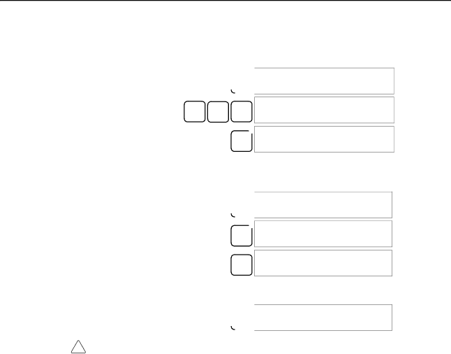
3.Clear the CPM1A’s memory by pressing the CLR, SET, NOT, RESET, and then the MONTR Key. Press the CLR Key several times if memory errors are displayed.

00000

CLR

SET NOT RESET

00000MEMORY CLR?

HR CNT DM

00000MEMORY CLR

MONTR END HR CNT DM

4.Display and clear error messages by pressing the CLR, FUN, and then the MONTR Key. Continue pressing the MONTR Key until all error messages have been cleared.

00000

CLR

00000

FUN FUN (0??)

ERR/MSG CHK OK

MONTR

5.Press the CLR Key to bring up the initial programming display (program address 00000). The new program can be written at this point.

00000

CLR

!Caution Check the system thoroughly before starting or stopping the CPM1A to prevent any accidents that might occur when the program is first started.

102

Image 114
Contents CPM1A CPM1A Programmable Controllers Omron Product References  OmronTable of Contents Appendices About this Manual Precautions General Precautions Safety PrecautionsIntended Audience Operating Environment Precautions Application PrecautionsXiv Application Precautions Backup method Data Concepts EC DirectivesApplicable Directives Conformance to EC DirectivesXviii Section CPM1A Features and Functions 1 CPM1A FeaturesSection Standard Peripheral Devices Using the PTNT Link Communications CompoBus/S I/O Link Units Programming is PossibleExpansion I/O Units 2 I/O Terminal and IR Bit AllocationCPU Units Unit Relay output Transistor output Sink type Source typeControl Corresponding IR word Setting range BCD 3 CPM1A FunctionsSet value Word Word 001 or later PC model Input bits Response time Mode Function PC model Input bits Min. input pulse widthPulse output single-phase output Temperature Sensor Unit Functions CompoBus/S Slave Functions CPM1A-SRT21CPU Unit and Expansion Unit System ConfigurationCPU Unit and Expansion I/O Unit Configuration CPM1A CPU UnitsExpansion I/O Units Unit Max. number Inputs Outputs Model UnitsHost Link Communications Expansion UnitsConnecting to a Programmable TerminalOne-to-one PC Link Communications Adapters and CablesName Usage Model number CompoBus/S I/O Link Connections Name SpecificationsOne-to-one NT Link Communications Peripheral Device ConnectionsSysmac Support Software SYSMAC-CPT Support Name Model numberRevised Specifications Previous specifications New specifications Relevant pagesUnit Specifications and Components Specifications General SpecificationsCPM1A-10CDR-j CPM1A-20CDR-j CPM1A-30CDR-j CPM1A-40CDR-j Characteristics Memory Backup Increment Mode 5 kHz Max 3 I/O SpecificationsCPU Unit Input Specifications SpecificationExpansion I/O Unit Input Specifications CPU Unit and Expansion I/O Unit Output Specifications Relay Output20EDT 8ET Transistor Output Sink TypeTransistor Output Source Type 10CDT1-D 20CDT1-D 30CDT1-D 40CDT1-D 20EDT1 8ET1Communications Adapter Specifications RS-232C Adapter SpecificationsRS-422 Adapter Specifications CPM1A-10CDR-j/10CDT-D/10CDT1-D 10 I/O Terminals Unit ComponentsCPU Unit Components CPM1A-40CDR-j/40CDT-D/40CDT1-D 40 I/O TerminalsIndicator Status Meaning Fatal error Input indicatorsCPU Unit Component Descriptions Expansion I/O Unit with 8 Input Terminals Expansion I/O Unit ComponentsExpansion I/O Unit with 20 I/O Terminals Expansion I/O Unit with 8 Output TerminalsTemperature Sensor Unit Components Analog I/O Unit ComponentsSet value Thermocouple Range C Range F CPM1A-TS001/002CPM1A-TS101/102 Set value Platinum resistance Range C Range FPins Function CompoBus/S I/O Link Unit ComponentsCommunications Adapter Components RS-232C AdapterRS-422 Adapter Installation and Wiring Power Supply Voltage Design PrecautionsPower Supply Wiring 4 CPM1A Power InterruptionsMomentary Power Failure Detection Selecting an Installation SiteInstallation Site Conditions Automatic RestartPanel/Cabinet Installation Overheating1 CPM1A Orientation Installing the CPM1A2 CPM1A Installation CorrectDIN Track Installation Connecting an Expansion I/O Unit InstallationRemoval Section Line Noise Wiring and ConnectionsGeneral Precautions for Wiring Hanging DuctsConduits Ground WiringFloor Ducts GroundingCrimp Connectors To 240-VAC Power SupplyVDC Power Supply Input Wiring Input ConfigurationCPM1A-8ED Input Wiring Example OutputsDevice Circuit diagram Input DevicesInductive Loads Output Wiring Relay Output WiringOutput Configurations CPM1A-8ER Transistor Output Wiring Sink Type CPM1A-8ET Transistor Output Wiring Source Type CPM1A-40CDT1-DPolarity of Power Supply for the Load Output Short ProtectionInrush Current Considerations Fuse InsertionPeripheral Device Connection Host Link ConnectionsOne-to-one Host Link Connection One-to-N Host Link Connection RDB SDB RDA SDA One-to-one PC Link Connections One-to-one NT Link Connections C200HX/HG/HE PC Using Peripheral Devices SSS System Setup 2 CPM1A Restrictions and PrecautionsSupport Software Capabilities Offline Operations Online EditingFill Group Name Description Go ToCopy PrintGroup Name Description Utility Data Area Lists File Time ChartPC Setup ChangeOnline Operations Offline and Online Operations CQM1-PRO01-E Using a Programming ConsoleCompatible Programming Consoles C200H-PRO27-EDifferent Keys Mode SwitchBuzzer Volume Contrast ControlMonitor Mode Changing the CPM1A’s Mode with the Mode SwitchProgram Mode RUN ModeConnecting the Programming Console Panel InstallationEntering the Password Preparation for OperationProgram Password Program BZ Programming Console Operations OverviewClearing Memory All ClearPartial Clear Reading/Clearing Error Messages Buzzer OperationKey Sequence OFF Entering or Editing Programs Writing Hexadecimal, BCD Constant Writing a Word AddressWriting an Unsigned Decimal Number #FFF6Writing a Word Address DM Instruction Search Bit Operand Search00207INSERT END Not Inserting and Deleting InstructionsInsertion Deletion00178CIRCUIT ERR Checking the ProgramDelete END Corrected ProgramCont 11 Bit, Digit, Word MonitorBit Monitor Word MonitorMultiple Address Monitoring Channel LRCLR Channel LR @OFF OFF OFF Differentiation MonitorBinary Monitor CLR OFF OFF OFFThree-word Monitor Signed Decimal Monitor Unsigned Decimal MonitorChanging Timer, Counter SV Three-word Data Modification3CH CHG? Hexadecimal, BCD Data Modification Inputting a New SV ConstantIncrementing and Decrementing a Constant Binary Data Modification Pres VAL?Montr Signed Decimal Data Modification D0000 Montr Force Set, Reset Unsigned Decimal Data ModificationOn on Clear Force Set/ResetHex-ASCII Display Change 00000FORCE RELE?Displaying the Cycle Time Program PasswordProgramming Example Preparatory Operations00000MEMORY CLR? HR CNT DM Montr END HR CNT DM Programming Procedures Example ProgramInputting the Self-holding Bit Programming ProceduresInputting the One-second Timer Write NOPInputting the Two-second Timer Inputting the 10-count CounterLD not Inputting the Flicker OutputInputting the END001 Instruction Test Run in Monitor Mode Monitor BZTest Runs and Error Processing Initial System Checks Initial System Checks and Test Run Procedure2 CPM1A Test Run Procedure Points to checkFlash Memory Precautions Error CPM1A CycleSelf-diagnosis Functions Non-fatal ErrorsFatal Errors Message FAL No Meaning and appropriate responseError Messages Identifying ErrorsUser-defined Errors Error FlagsFALS07 Programming Console Operation ErrorsProgramming Errors Message MSG46Type Message Meaning and appropriate response Circuit ERRTroubleshooting Flowcharts Main CheckPower Supply Check Fatal Error Check Follow the Memory ErrorNon-fatal Error Check 121 122 Environmental Conditions Check Memory Error Check Inspection Items Maintenance InspectionsPower supply Allowable voltage fluctuation range Inspection items Details Criteria RemarksStandard Tools Handling PrecautionsNecessary Tools for Inspection Measurement DevicesExpansion Memory Unit Memory Areas PrecautionsOverview ButtonSpecifications and Nomenclature SpecificationsNomenclature Mounting/Removing Eeprom LED IndicatorHandling Mounting EepromCPM1, CPM1A, CPM2A Peripheral Port Communications SettingsPC Connections CQM1, and SRM1 PCsDisconnecting Uploading ProgramsOperation Procedure Downloading Programs134 135 CPU Units Standard ModelsExpansion Units Expansion I/O UnitsCompoBus/S I/O Link Unit Temperature Sensor UnitsDescription Specifications Model number Communications AdaptersName Appearance Model Number Specifications Peripheral DevicesCPM1A-20CDR-j/20CDT-D/20CDT1-D CPU Unit DimensionsCPM1A-10CDR-j/10CDT-D/10CDT1-D CPU Unit CPM1A-30CDR-j/30CDT-D/30CDT1-D CPU UnitCPM1A-40CDR-j/40CDT-D/40CDT1-D CPU Unit CPM1A-20EDjExpansion I/O UnitCPM1A-8jjjExpansion I/O Unit CPM1A-TSjjjTemperature Sensor Unit CPM1A-MAD01 Analog I/O UnitCPM1A-SRT21 CompoBus/S I/O Link Unit CPM1-CIF01 RS-232C Adapter CPM1-CIF11 RS-422 AdapterDimensions with Peripheral Devices Attached Appendix BAUTOEXEC.BAT ACPAscii BCDBit-control instruction Bit designatorBit number BlockCONFIG.SYS CTSData link DefaultDIP switch Data link areaEeprom EpromFCS Input signal DelayInitialization error InstallJIS LEDLSS Not OFFPCB Prom RAMRAS ROM SCPSSS System error Syntax errorSystem configuration System error messageWDT Numbers Index 165 166 167 Revision code Date Revised content Revision History
Related manuals
Manual 6 pages 62.26 Kb