Installation, Operation & Maintenance | HTV/HTD/HTH SERIES | Heat Controller, Inc. |
Field Conversion of Air Discharge
Overview - Horizontal units can be field converted between side (straight) and back (end) discharge using the instructions below.
Note: It is not possible to field convert return air between left or right return models due to the necessity of refrigeration copper piping changes.
Preparation - It is best to field convert the unit on the ground before hanging. If the unit is already hung it should be taken down for the field conversion.
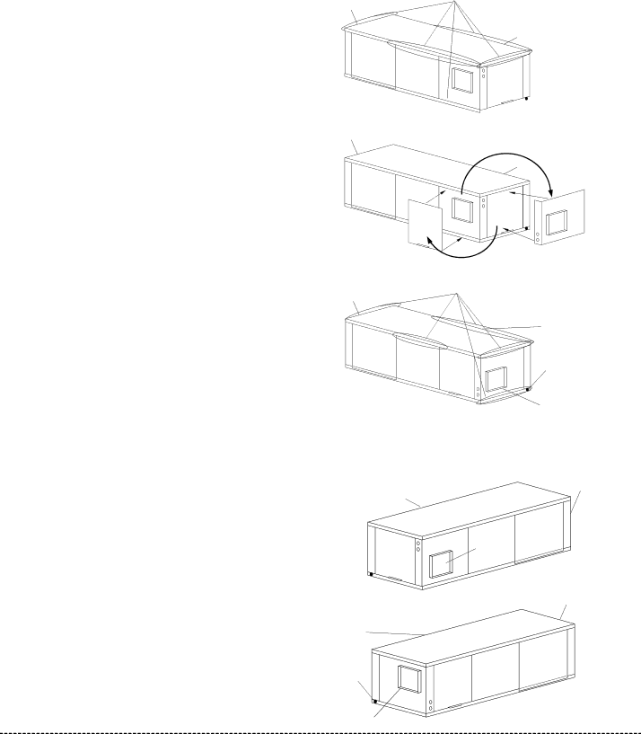
Side to Back Discharge Conversion
1. Place unit in well lit area. Remove the screws as shown in |
Figure 4 to free top panel and discharge panel. |
Figure 4: Left Return Side to Back
Water | Remove Screws |
Connection End |
|
Return Air
Side Discharge ![]()
![]()
Water
Connection End
2. | Lift out the access panel and set aside. Lift and rotate the |
| discharge panel to the other position as shown, being careful |
| with the blower wiring. |
3. | Check blower wire routing and connections for tension or |
| contact with sheet metal edges. Reroute if necessary. |
4. | Check refrigerant tubing for contact with |
| other components. |
5. | Reinstall top panel and screws noting that the location for |
| some screws will have changed. |
6. | Manually spin the fan wheel to ensure that the wheel is not |
| rubbing or obstructed. |
Water
Rotate
Return Air
Move to Side
Replace Screws
7. | Replace access panels. |
Back to Side Discharge Conversion - If the discharge is changed from back to side, use above instruction noting that illustrations will be reversed.
Left vs. Right Return - It is not possible to field convert return air between left or right return models due to the necessity of refrigera- tion copper piping changes. However, the conversion process of side to back or back to side discharge for either right or left return configuration is the same. In some cases, it may be possible to rotate the entire unit 180 degrees if the return air connection needs
Connection End
Back Discharge
Return Air
Drain
Discharge Air
to be on the opposite side. Note that rotating the unit will move the piping to the other end of the unit.
Figure 5: Right Return Side to Back
Return Air
Supply Duct
Side Discharge
Water
Connection End
Water
Return Air
Drain
Discharge Air
Connection End
Back Discharge
7