Agilent Technologies Low-Profile Modular Power System
Legal Notices
Agilent Technologies, Inc
Safety Notices
General
This Book
Contents
103
Agilent Models N6751A/N6752A, N6753A/N6754A, N6761A/N6762A
100
104
Modular Power System MPS
Essential operating features of the power system
Referred to as MPS and power system throughout this manual
Agilent N6700 Modular Power System At a Glance
Output Features
System Features
Model Differences
Front Panel At a Glance
Rear Panel At a Glance
Single-channel view
Indicators
Front Panel Display At a Glance
Interface status
Front Panel Keys At a Glance
Operating status
Number keys
Front Panel Menu Reference
OCP
USB
Scpi Command Summary
Subsystem Commands
Scpi Command Description
Scpi Command
FUNCtion VOLTage CURRent, @chanlist SWEep
ALL
Command Description
Common Commands
RST Settings
These settings are set by the *RST Reset command
Installation
Items Supplied
General Information
Models
Options
Rack Installation
Installing the Unit
Safety Considerations
Inspecting the Unit
Installation
Channel Number
Bench Installation
Cleaning
Hz Operation
Power cord, resulting in fire
Connecting the Line Cord
Installation
Snap-On Ferrite Core
Terminals. Sense jumpers are provided for local sensing
Connecting the Outputs
Screws securely tightened
Terminals in any other way
Wire Size
AWG
Multiple Loads
Response Time with an External Capacitor
Positive and Negative Voltages
N6700 Modular Power System Scope
Remote Sense Connections
Drop in the sense leads can degrade the voltage regulation
Over-voltage Protection Considerations
Parallel Connections
Open Sense Leads
Output Noise Considerations
Firmware revision B.00.00 and up
When programming via the front panel or using Scpi commands
Grouping the Outputs
Discussed in under System-Related Operations
Series Connections
Effect on Specifications
Recovery Time
Terminal may be more than 240 VDC from chassis ground
Setting the Outputs
Desired operating voltage
Effect on Specifications
Getting Started
Menu structure is found in Chapter
Selecting an Output Channel
Entering an Output Voltage Setting
Turning the Unit On
Method 1 Use the Navigation and Arrow Keys
Enabling the Output
Entering a Current Limit Setting
Use the On/Off key to enable the output
Method 2 Use the Current key to enter a value
Set the Over-Voltage Protection
Using the Front Panel Menu
Press the Menu key to access the front panel command menu
Menu
Case of Trouble
Exiting the Command Menu
Meter Back There are two ways to exit the command menu
Enter Channel
Gpib Interface
Connecting to the Interfaces
Cause the unit to reset and require operator intervention
Automation-Ready CD that is shipped with your product
LAN Interface
USB-enabled instrument to the Universal Serial Bus USB.
USB Interface
Following figure illustrates a typical USB interface system
Connecting to a Site LAN
Connecting to a Private LAN
Dhcp server. You can leave these settings as they are. Most
Release the previous settings
Factory-shipped instrument LAN settings are configured to
Will come on when the LAN port has been configured
LAN Parameters
Viewing the Currently Active LAN Settings
Configuring the LAN Parameters
Take effect
Name
Domain
Reset
LAN Communication
Using the Web Server
Reduced
Using Telnet
Using Sockets
Telnet connections to be made
Enable/Disable the USB, LAN, and Web Server
Restoring the Non-volatile Factory Settings
Securing the Interfaces
Factory-shipped non-volatile LAN settings
Other factory-shipped non-volatile settings
Operating the Power System
Set the Output Voltage
Programming the Output
Select an Output Channel
Set the Voltage Slew Rate
Sequence Multiple Outputs
Enable the Output
Set the Output Current
Outpdelrise .1,@2
Outp
Front Panel Scpi Command Select Output\Polarity
Program the Output Relays
Outprelpol REV,@1
Front Panel Scpi Command Select Transient\Step
Enable the Output to Respond to Trigger Commands
Front Panel Scpi Command Select Transient\Mode
Synchronizing Output Steps
Select the Transient Trigger Source
Initiate the Transient Trigger System
Trigger the Output
Generate Trigger Out Signals
Front Panel Scpi Command Select Transient\Control
Scroll to and select Abort
Making Measurements
Simultaneous Voltage and Current Measurements
Measurement Ranges
Set the Over-Current Protection
Using the Protection Functions
Front Panel Scpi Command Select Protect\OVP
Enter a value in the OVP level box To 10 Press Select
Couple Output Protection
Clear Output Protection Functions
Instrument Identification
System-Related Operations
Self-Test
Instrument State Storage
Systgrodelall
Front Panel Scpi Command Select System\Groups
Output Groups
Systreb
Front Panel Keys
Front Panel Scpi Command Select System\Preferences\Lock
Front Panel Scpi Command Select System\Preferences\Keys
Lockout
Contrast
Front Panel Display
Screen Saver
View
List Function
When the power system is turned off
Programming High-Speed Test Extensions
All models Refer to , Model Differences
Program an Output Pulse or Pulse Train
Front Panel Scpi Command Select Transient\List\Config
Front Panel Scpi Command Select Transient\List\Pace
Voltmode LIST, @1
Trigtransour BUS, @1
Front Panel Scpi Command Select Transient\List\Repeat
Front Panel Scpi Command Select Transient\TrigSource
Inittran @1
Program an Arbitrary List
Select the List Step number
Front Panel Scpi Command Select the Transient\List\Repeat
Liststep AUTO, @1
Digitizer Function
Adjust the Measurement Sample Rate
Front Panel Scpi Command Select Measure\Sweep
Programming the Digitizer
Specify a Window Function
Acquisition trigger, use
To offset the measurement on
Synchronizing Digitizer Measurements
Front Panel Scpi Command Select Measure\Window
Front Panel Scpi Command Not Available
Retrieve Measurement Array Data
Sensfunc CURR,@14
Select the Measurement Trigger Source
Sensfunc VOLT,@14
Transientn
Trigger the Measurement
Front Panel Scpi Command Select Measure\Control
Initiate the Measurement Trigger System
Trigacq @1
Appendix a Specifications
Performance Specifications
Agilent Models N6751A/N6752A, N6753A/N6754A, N6761A/N6762A
Supplemental Characteristics
Down-programming Settling Time with no load
Up-programming Time with full resistive load
Up-programming Settling Time with full resistive load
Down-programming Time with Capacitive load
Autoranging Characteristic
Output Impedance Graphs
Model N6753A, CV Mode, @20V, 15A
0125 Magnitude
Load Transient Recovery Time
Agilent Models N6731B N6736B and N6741B N6746B
Temperature Coefficient per C
Common Mode Noise
From 20 Hz 20 MHz from either output to chassis
Agilent Models N6773A N6776A
20 mA
Agilent N6700B, N6701A, N6702A MPS Mainframes
Environmental Conditions
Dimensions
Net Weight
AC Input
Outline Diagram
432.5 mm 17.03 482.6 mm 19.00 425.45 mm
Appendix B Using the Digital Port
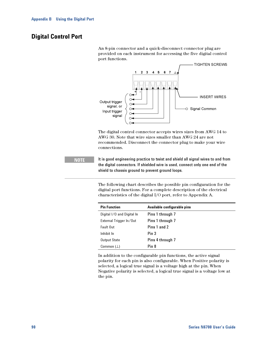
Digital Control Port
Pin Bit
Configuring the Digital Control Port
Bi-directional Digital I/O
Select System\IO\DigPort\Pinn
Front Panel Scpi Command Select System\IO\DigPort\Pinn
Digital Input
External Trigger
Front Panel Scpi Command Select System\IO\DigPort\Pin3
Fault Output
Front Panel Scpi Command Select System\IO\DigPort\Pin1
Inhibit Input
Fault/Inhibit System Protection
Clearing a System Protection Fault
Mainframes
Power rating of Agilent N6700 mainframes is as follows
This chapter discusses the power allocation function
For the majority of Agilent N6700 Modular Power System
Rating of the mainframe
Module Power Limit
Power Limit Operation
Mainframe Power Limit
Must reset the power limit to its maximum rated value
Module Power Allocation
To set a power limit on output
Power limit function will not activate
Page
Appendix D Output On/Off Synchronization
Synchronizing Output Turn-on Delays
Power Modules Options and Mode Minimum
Tutorial
Outpcoup on
Procedure
Enable the Synchronization Function
Outpcoup OFF
Specify the Turn-On Delays for each Output Channel
Specify the Common Delay Offset
Specify which Output Channels will be Synchronized
Digital Connections and Configuration
Synchronizing Multiple Mainframes
DIGPIN6FUNC ONC
Operation
System\IO\DigPort\Pin6
DIGPIN7FUNC Offc
Index
11, 42
Inhibit input
Instrument
List
Specifications
Remote interface
System protection
Declaration of Conformity
Manual Updates