Alesis
Important Safety Instructions
Grounding Instructions
Page
Contents
Editing Mixes
Editing Effects
Index
Unpacking and Inspection
Setting UP
AC Power Hookup
Line Conditioners and Protectors
Setting Up Chapter QuadraSynth Plus Piano Reference Manual
About Audio Cables
Basic Audio Hookup
Page
Word About Sound Bridge
Your First Session with the Quadrasynth Plus
Powering Up
Adjusting the Display Contrast
Page
Playing Specific Sections of the Demo
Enabling General Midi Mode
Playing the Demo Sequence
Program Mode and Mix Mode
Playing the QuadraSynth Plus
Page
Selecting the Midi Channel
Auditioning Internal Programs
Selecting Banks
¿ Use the Midi and ∅ buttons to select a Midi channel from
Realtime Performance Functions
Quad Knobs
Auditioning Mix Play Mode
Display will change to Mix Play Mode
Page
Editing a Mix
Top line of the LCD’s function list will read Editing MIX
QuadraSynth Plus Piano Reference Manual
Setting the Effects Level
Display will indicate Sound 1 2 3
Page
Connections
Basic Midi Hookup
Example 1 Master Controller for Live Use
Example 2 Using an External Sequencer
Page
Pedal and Footswitch Hookup
About the Keyboard Mode
Connections Chapter
Recording Digital Audio
Digital Audio/Optical Hookup
KHz Clock
Page
QuadraSynth Plus Polyphony
Overview
Basic Architecture
Program Edit Mode
Program Play Mode
Mix Play Mode
Modes
Global Edit Mode
Mix Edit Mode
Effects Edit Mode
Store Mode
Page
User Interface Display, Functions, Pages, and Parameters
About the Display
Midi Buttons
Quad Knob Editing
Parameter Editing
Page
Direct Function Selection
Editing Program Parameters
Edit 4 and Edit 1 Modes
Status line in the display will indicate Sound 1 2 3
Page
Comparing Edited and Stored Versions
Preset Memory and User Memory
Resetting a Parameter Value
Page
Storing
Store a Program
QuadraSynth Plus Piano Reference Manual
Store a Mix
Copying Effects Between Programs
Store an Effect
Overview Chapter
To Audition Programs Before Storing
Overview Chapter
Page
Overview Chapter QuadraSynth Plus Piano Reference Manual
Editing Mixes
What is a Mix?
Mix Edit Mode
Understanding the Edit Buffers
Page
Level Setting for Each Program
Program Assign for each Midi Channel
Page
Range
Setting the Range and Midi Switches
Pitch
Page
Transmitting Midi Volume and Panning
Effect
Effects in Mix Play Mode
Effect Level
Naming a Mix
FX Midi On or Off
Setting Midi Out Channels for Mix in Global Mode
Polyphony in Mix Play Mode
Using the QuadraSynth Plus as a Master Keyboard
Page
Normalized Synth Voice
Editing Programs
Overview
How the QuadraSynth Generates Sound
Program Sound Layers
QuadraSynth Plus Signal Flow
Four Sounds of a Program
Voice
Lowpass Filter
About Modulation
Amp
Page
Envelopes
About Signal Processing
LFO Low Frequency Oscillator
Drum Mode
Page
Group 16 options
Program Edit Functions
Assign Voice
Name
Group Voice
Pan 3 to
Volume 00 to
Level
Output Main, Aux, or Off
Pitch
Pitch
Pitch LFO Depth -99 to +99
Pitch Envelope Depth -99 to +99
Portamento Exponential, Linear, 1 Speed
Keyboard Mode Mono, Poly, 1-Pitch or 1-PMono
Rate 0 to
Keyboard Track On or Off
Filter
Filter Frequency 00 to
Velocity -99 to +99
Page
Filter Envelope Depth -99 to +99
Filter Modulation Wheel Depth -99 to +99
Filter LFO Depth -99 to +99
Velocity Curve 13 choices
Amplitude LFO Depth -99 to +99
Page
Sound Overlap 00 to
Page
Selecting the Modulator 1 to
Mod
About General Purpose Modulation
Modulation Source
Page
Page
Modulation Destination
Alfo
Modulation Level -99 to +99
Gate Mode Off or On
Quantize Mode Off or On
Pitch LFO
Pitch LFO Level 00 to
Mod Wheel -99 to
Aftertouch -99 to
Filter LFO Level 00 to
Filter LFO
Filter LFO
Trigger Mono, Poly, Key Mono, Key Poly
Amp LFO
Amp LFO
Page
Pitch Envelope
Pitch Envelope
Amp LFO Level 00 to
Attack 00 to
Page
Release 00 to 99, Hold
Pitch Envelope Delay 00 to 99, Hold
Decay & Sustain 00 to
Pitch Envelope Time Tracking On or Off
Trigger Normal, Freerun, Reset, Reset-Freerun
Sustain Decay 00 to
Sustain Pedal On or Off
Level 00 to
Filter Envelope
Filter Envelope
Velocity Modulation 00 to
Release 00 to
Filter Envelope Delay 00 to
Filter Envelope Time Tracking On or Off
Page
Amp Envelope
Amp Envelope
Amp Envelope Delay 00 to
Amp Envelope Time Tracking On or Off
Level 00 to
Tracking Generator
Input
Plfo Flfo Alfo Penv Fenv Aenv
Name
Points 0 10
Misc
Drum Mode
Sound Enable
Programming Drum Sounds
VelocityFilter 0 to
Effects Level
Pitch -12.00 to +12.00
Range 0 to +3
Decay 0 to 99, Gate00 to Gate99
Mute Group Off, 1, 2, or
Copying Sounds
Copying Effects
Initializing Programs
Editing Effects
Selecting Effects in Mix Mode
Setting Effects Send Levels
Page
Clip
Editing Effects
Storing Effect Patches In Program Mode
Storing Effect Patches in Mix Mode
Page
Configurations
Copying Effect Patches
Page
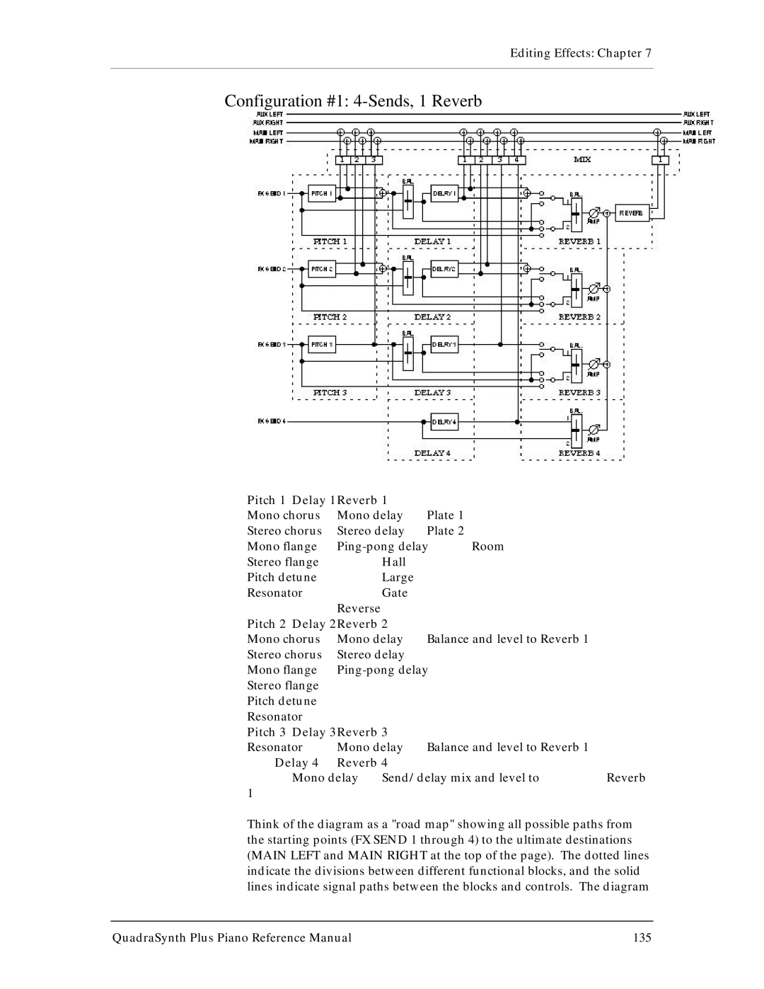
Configuration #1 4-Sends, 1 Reverb
Pitch 1 Delay 1Reverb
Page
Configuration #2 4-Sends, 2 Reverb
Page
Configuration #3 4-Sends, 1 Lezlie
Page
Configuration #4 2-Sends, with EQ
Pitch 1 Delay 1Reverb Misc
Configuration #5 Odchsddlrevlz
Reverb
Reverb
Input Balance
Send Input Levels
Input level
Chorus Input Level
Page
Reverb Type
Page
Input Filter
Pre-Delay Time
Pre-Delay Mix
Decay
Page
Density
Diffusion
Delay Pages 2
Delay
Delay
Page
Pitch Type
Page
Page
Delay Input
Speed
Resonator Tuning and Decay
Waveform Shape
Depth
Mod Source
Mod
Selecting the Modulator
Mod Destination
Mod Level
Delay Level
Mix
Pitch Level
Overdrive
Misc
Reverb Level
Overdrive Type
Overdrive Balance
Overdrive Threshold
Overdrive Brightness
Page
Enabling General Midi Mode via Midi
Global Settings
General Midi Mode
Editing Global Parameters
Keyboard Sensitivity
Master Pitch and Master Tuning
Keyboard Mode
Keyboard Curve
Reset Controllers a D
Controllers a D Assignment
Controllers a D Mode
Midi Program Select
Using Pedals to Control Volume or Modulation
Pedal 1 and 2 Assignment
Receiving and Transmitting Bank Change Message
Edit Mode
KHz Clock Input
Loading a Bank from an External Card
Midi Transfer and Storage Operations
Saving the User Bank to an External Card
Storing an Individual Program or Mix to an External Card
Loading an Individual Program or Mix from an External Card
Saving Programs via Midi Sys Ex
Card Storage RAMifications
To send the entire User bank via Midi
Re-initializing
TROUBLE-SHOOTING
Trouble-Shooting Index
Maintenance/Service
Checking Software Version
Customers outside the USA
Page
Page
Midi Hardware
Midi Supplement
Midi Basics
Channel Messages Voice Messages
Channel Messages Mode Messages
Midi Message Basics
Page
Page
General Midi
System Common Messages
Page
Page
Midi Implementation Chart
Parameters Index
Program Parameters
Quad Parameter Function Knob Manual
Mix Parameters