For current information contact Analog Devices at (781) 461-3881


Y


R


A


ADSP-2192


N


L


I


M


A


I

C


L


If for some reason the host sends more data than the max-


E


I


packetsize, theNUSB core accepts it, as long as there is

R

H


P


sufficientCroom in theAFIFO.


E


T


T

A


Since the DSPDcontrols the read pointer, it must perform a

similar calculation to determine if there is sufficient data in the FIFO to begin processing. Once it has consumed some amount of data, the DSP will need to update the Memory Buffer Read Offset register.

IN Transactions (Host <- Device)

When an IN transaction arrives for a particular endpoint, the USB core once again computes how much read data is available in the FIFO. It also determines if the amount of read data is greater than or equal to the maxpacketsize. If both conditions are met, the USB core will transfer the data. Upon receiving ACK from the host, the USB core updates the Memory Buffer Read Offset register.

If the amount of read data is less than the maxpacketsize (a short packet), the USB core determines whether to send the data based upon a NAK count limit. This is a 4-bit field in

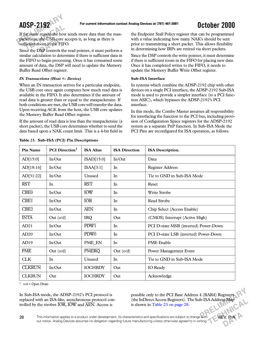
Table 23. Sub-ISA (PCI) Pin Descriptions

October 2000

the Endpoint Stall Policy register that can be programmed with a value indicating how many NAK's should be sent prior to transmitting a short packet. This allows flexibility in determining how IRPs are retired via short packets.

Since the DSP controls the write pointer, it must determine if there is sufficient room in the FIFO for placing new data. Once it has completed writes to the FIFO, it needs to update the Memory Buffer Write Offset register.

Sub-ISA Interface

In systems which combine the ADSP-2192 chip with other devices on a single PCI interface, the ADSP-2192 Sub-ISA mode is used to provide a simpler interface (to a PCI func- tion ASIC), which bypasses the ADSP-2192’s PCI interface.

In this mode, the Combo Master assumes all responsibility for interfacing the function to the PCI bus, including provi- sion of Configuration Space registers for the ADSP-2192 system as a separate PnP function. In Sub-ISA Mode the PCI Pins are reconfigured for ISA operation, as follows.


Pin Name

PCI Direction1


ISA Alias

ISA Direction

ISA Description.


AD[15:0]

In/Out


ISAD[15:0]

In/Out

Data


AD[18:16]

In/Out


ISAA[3:1]

In

Register Address


AD[31:22]

In/Out


Unused

In

Tie to GND in Sub-ISA Mode


In


In

Reset


RST

RST


In/Out


In

Write Strobe


CBE0


IOW


In/Out


In

Read Strobe


CBE1


IOR


In/Out


In

Chip Select (Access Enable)


CBE2


AEN


Out (o/d)

IRQ

Out

(CMOS) Interrupt (Active High)


INTA


AD21

In/Out


In

PCI D-state MSB (inverted) Power-Down


PDW1


AD20

In/Out


In

PCI D-state LSB (inverted) Power-Down


PDW0


AD19

In/Out


PME_EN

In

PME Enable


Out (o/d)


Out (o/d)

Power Management Event


PME


PMERQ


CLK

In


Unused

In

Tie to GND in Sub-ISA Mode


In/Out


IOCHRDY

Out

IO Ready


CLKRUN


CLKRUN

Out

IOCHRDY

Out

Acknowledge


1o/d = Open Drain


Y

In Sub-ISA mode, the ADSP-2192’s PCI protocol is

possible only to the PCI Base Address 4 (BAR4) Registers

R

replaced with an ISA-like, asynchronous protocol con-


A


(the InDirect Access Registers). The Sub-ISA Address Map


N


L


I


trolled by the strobes IOR, IOW and AEN. Access is

is shown in Table 23 on page 28.


M


A


I


C


L


E


I


N


28


R


H


This information applies to a product under development. Its characteristics and specifications are subject to changePwith-


CREV. PrA A


out notice. Analog Devices assumes no obligation regarding future manufacturing unless otherwise agreed to in writing.

E


T


A


T


D


Page 28
Image 28
Analog Devices ADSP-2192 If for some reason the host sends more data than the max, SufficientCroom in theAFIFO

ADSP-2192 specifications

The Analog Devices ADSP-2192 is a high-performance digital signal processor (DSP) that stands out in the realm of signal processing applications. The device is part of the ADSP-2100 family, which has been recognized for its ability to deliver high-speed computations and efficient processing capabilities. The ADSP-2192 is particularly well-suited for applications requiring advanced digital signal processing, such as telecommunications, audio processing, and industrial control systems.

One of the key features of the ADSP-2192 is its dual-core architecture. This allows for parallel processing capabilities, enabling the device to handle multiple tasks simultaneously. Each core can execute instructions independently, which significantly boosts the overall processing power. The device is built on a 16-bit architecture, supporting 16-bit fixed-point and 40-bit floating-point operations, allowing for a wide range of precision in calculations.

The ADSP-2192 also incorporates a sophisticated instruction set designed for efficient performance. It includes specialized instructions tailored for common signal processing tasks, such as filtering and Fourier transforms. This optimized instruction set enhances the speed and efficiency of data manipulation and computation, making it an ideal choice for real-time applications.

In terms of memory, the ADSP-2192 is equipped with 1 KB of on-chip program memory and 2 KB of data memory. This provides sufficient storage for handling complex algorithms without the need for external memory, reducing latency and increasing processing speed. The device also supports external memory interfaces, enabling developers to expand the system's memory capacity if needed.

Another standout feature of the ADSP-2192 is its rich set of communication interfaces. It supports a variety of communication protocols, including SPI, USART, and I2C, facilitating seamless integration with other devices and systems. This versatility makes it suitable for a wide range of applications, from consumer electronics to industrial automation.

In terms of power consumption, the ADSP-2192 is designed to be energy-efficient, making it an excellent choice for battery-operated devices and applications requiring low power usage. The device operates at a voltage range of 3V to 5V, making it compatible with various power supply systems.

Overall, the Analog Devices ADSP-2192 combines powerful processing capabilities with efficient resource management and versatility, making it a strong contender in the DSP market. Its dual-core architecture, robust instruction set, communication flexibility, and energy-efficient design position it as an essential component for advanced signal processing applications across multiple industries.