Y


R


October 2000


A


ADSP-2192


For current information contact Analog Devices at (781) 461-3881


N

L


I


M


A


I

C


L


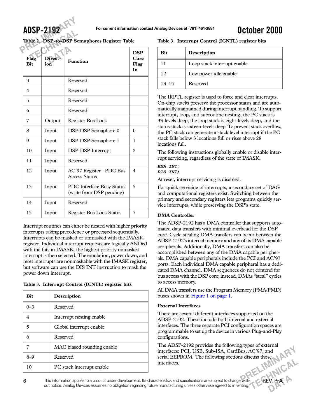
Table 3. Interrupt Control (ICNTL) register bits


Table 2. DSP-to-DSP Semaphores Register Table


E


I


N


R


H


P

C


A

DSP


Bit

Description


E


T


FlagT

DirectA-

Function

Core


Bit


D


Flag

11

Loop stack interrupt enable


ion


In


12

Low power idle enable

3


Reserved


4


Reserved


5


Reserved


6


Reserved


7

Output

Register Bus Lock


8

Input

DSP-DSP Semaphore 0

0


9

Input

DSP-DSP Semaphore 1

1


10

Input

DSP-DSP Interrupt

2


11

Input

Reserved


12

Input

AC’97 Register - PDC Bus

4


Access Status


13

Input

PDC Interface Busy Status

5


(write from DSP pending)


14

Input

Reserved


15

Input

Register Bus Lock Status

7

13–15

Reserved

The IRPTL register is used to force and clear interrupts. On-chip stacks preserve the processor status and are auto- matically maintained during interrupt handling. To support interrupt, loop, and subroutine nesting, the PC stack is

33-levels deep, the loop stack is eight-levels deep, and the status stack is sixteen-levels deep. To prevent stack overflow, the PC stack can generate a stack level interrupt if the PC stack falls below 3 locations full or rises above 28 locations full.

The following instructions globally enable or disable inter- rupt servicing, regardless of the state of IMASK.

ENA INT;

DIS INT;

At reset, interrupt servicing is disabled.

For quick servicing of interrupts, a secondary set of DAG and computational registers exist. Switching between the primary and secondary registers lets programs quickly ser- vice interrupts, while preserving the DSP’s state.

DMA Controller

Interrupt routines can either be nested with higher priority

The ADSP-2192 has a DMA controller that supports auto-


mated data transfers with minimal overhead for the DSP


interrupts taking precedence or processed sequentially.


core. Cycle stealing DMA transfers can occur between the


Interrupts can be masked or unmasked with the IMASK


ADSP-2192’s internal memory and any of its DMA capable


register. Individual interrupt requests are logically ANDed


peripherals. Additionally, DMA transfers can also be


with the bits in IMASK; the highest priority unmasked


accomplished between any of the DMA capable peripher-


interrupt is then selected. The emulation, power down, and


als. DMA capable peripherals include the PCI and AC’97


reset interrupts are nonmaskable with the IMASK register,


ports. Each individual DMA capable peripheral has a dedi-


but software can use the DIS INT instruction to mask the


cated DMA channel. DMA sequences do not contend for


power down interrupt.


bus access with the DSP core; instead, DMAs “steal” cycles


Table 3. Interrupt Control (ICNTL) register bits

to access memory.


All DMA transfers use the Program Memory (PMA/PMD)


Bit


Description

buses shown in Figure 1 on page 1.


External Interfaces


0–3


Reserved


There are several different interfaces supported on the


4


Interrupt nesting enable


ADSP-2192. These include both internal and external


5


Global interrupt enable

interfaces. The three separate PCI configuration spaces are


programmable to set up the device in various Plug-and-Play


6


Reserved


configurations.


The ADSP-2192 provides the following types of external


7


MAC biased rounding enable

Y


interfaces: PCI, USB, Sub-ISA, CardBus, AC’97, and


R

8–9


Reserved

serial EEPROM. The following sections discuss those

A


interfaces.


N

L


10


PC stack interrupt enable


I


A


M


L


IC


E


N


6


R


H


This information applies to a product under development. Its characteristics and specifications are subject to changePwith-


CREV. PrA A


out notice. Analog Devices assumes no obligation regarding future manufacturing unless otherwise agreed to in writing.

E


T


A


T


D


Page 6
Image 6
Analog Devices ADSP-2192 specifications Loop stack interrupt enable

ADSP-2192 specifications

The Analog Devices ADSP-2192 is a high-performance digital signal processor (DSP) that stands out in the realm of signal processing applications. The device is part of the ADSP-2100 family, which has been recognized for its ability to deliver high-speed computations and efficient processing capabilities. The ADSP-2192 is particularly well-suited for applications requiring advanced digital signal processing, such as telecommunications, audio processing, and industrial control systems.

One of the key features of the ADSP-2192 is its dual-core architecture. This allows for parallel processing capabilities, enabling the device to handle multiple tasks simultaneously. Each core can execute instructions independently, which significantly boosts the overall processing power. The device is built on a 16-bit architecture, supporting 16-bit fixed-point and 40-bit floating-point operations, allowing for a wide range of precision in calculations.

The ADSP-2192 also incorporates a sophisticated instruction set designed for efficient performance. It includes specialized instructions tailored for common signal processing tasks, such as filtering and Fourier transforms. This optimized instruction set enhances the speed and efficiency of data manipulation and computation, making it an ideal choice for real-time applications.

In terms of memory, the ADSP-2192 is equipped with 1 KB of on-chip program memory and 2 KB of data memory. This provides sufficient storage for handling complex algorithms without the need for external memory, reducing latency and increasing processing speed. The device also supports external memory interfaces, enabling developers to expand the system's memory capacity if needed.

Another standout feature of the ADSP-2192 is its rich set of communication interfaces. It supports a variety of communication protocols, including SPI, USART, and I2C, facilitating seamless integration with other devices and systems. This versatility makes it suitable for a wide range of applications, from consumer electronics to industrial automation.

In terms of power consumption, the ADSP-2192 is designed to be energy-efficient, making it an excellent choice for battery-operated devices and applications requiring low power usage. The device operates at a voltage range of 3V to 5V, making it compatible with various power supply systems.

Overall, the Analog Devices ADSP-2192 combines powerful processing capabilities with efficient resource management and versatility, making it a strong contender in the DSP market. Its dual-core architecture, robust instruction set, communication flexibility, and energy-efficient design position it as an essential component for advanced signal processing applications across multiple industries.