Manuals
/
APC
/
Computer Equipment
/
Power Supply
APC
9000
installation manual
Mgetm GalaxyTM, Installation manual
Models:
9000
1
1
40
40
Download
40 pages
47.73 Kb
1
2
3
4
5
6
7
8
Characteristics
Install
Power circuit wiring diagrams
Temperature Monitor base
Connection of power circuits
Static Switch Cubicle
Page 1
Image 1
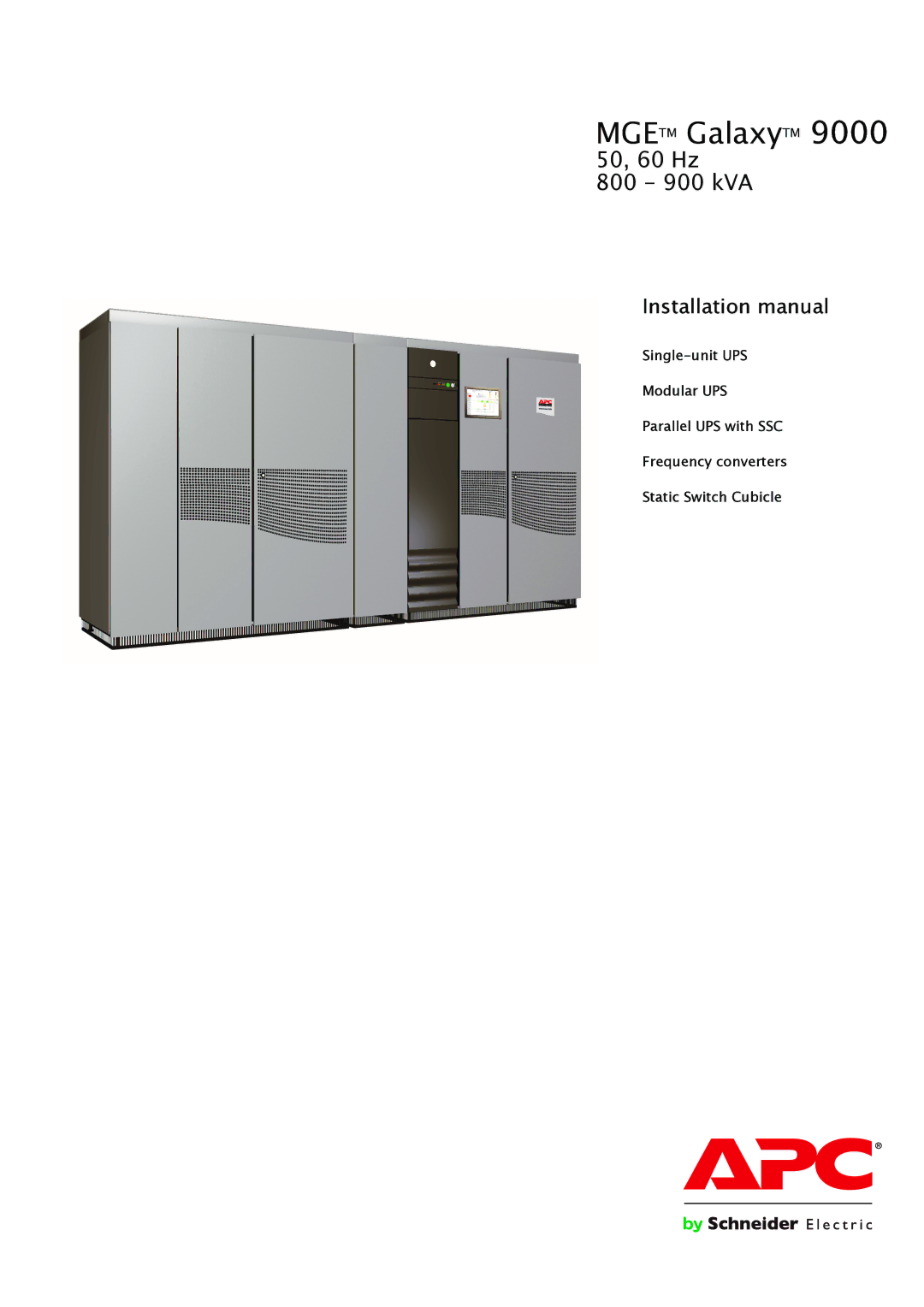
MGE
TM
Galaxy
TM
9000
50, 60 Hz
800 - 900 kVA
Installation manual
Single-unit
UPS
Modular UPS
Parallel UPS with SSC
Frequency converters
Static Switch Cubicle
Page 1
Page 2
Page 1
Image 1
Page 1
Page 2
Contents
Mgetm GalaxyTM
Installation manual
34006451EN/AC
Contents
Characteristics common to all cubicles
Characteristics
Characteristics of rectifier-inverter cubicles
Static Switch Cubicle
Characteristics of Static Switch Cubicles
Rectifier-inverter cubicle
Electrical parameters for Mains
Electrical parameters for selecting protective devices
Electrical parameters for Mains 2 415
Rated Mains 1 current Inverter
Parameters for single-unit UPS cables
Electrical parameters for determining cable cross-sections
Installation with parallel UPSs with a centralised SSC
Installation with parallel frequency converters
NF C 15-100 authorizes a maximum of 4 cables per phase
Maintenance Bypass cubicle Mains Inverter Mains 1 mains Load
Positioning the cubicles
Handing
Side clearances provided by the spacing uprights Rear
Front
Cubicle layout on false floor or normal floor figures 6, 7
Floor loads figure
Cubicle footpads Rear
Connection via the bottom
Layout for a single-unit UPS with one battery cubicle Rear
Diagram for a frequency converter with batteries
Power circuit wiring diagrams
Special case
Example of a 2 parallel UPS rectifier-inverters with SSC
Diagram for a frequency converter without batteries
Modular UPS cubicle
External maintenance bypass cubicle
Mounting of the left and right cubicles
Cubicle mounting and connection
XMGD05
Internal connections between cubicles
XFGD06
General
Connection of power circuits
Left cubicle of single-unit or parallel UPS with SSC
Cross-section AA
XR1 XR8
Right cubicle of single-unit UPS
XR9
XR2 XR5 XR3 XR6 XR4 XR7
Front Rear
Right cubicle of a parallel UPS with SSC
XR2 XR5
XR3 XR6 XR4 XR7
XR1 XR2 XR3 XR4
Connection of auxiliary circuits on the remote relay board
Emergency shutdown
Connection to battery circuit breaker QF1
Connections between Apoz boards
Connections between rectifier-inverter cubicles
XM XM XM XM
Misi
Connections between Misi boards modular UPSs
UPS
Misi
XR8 XR9 XR5 XR6 XR7
Acpz board of the Static Switch Cubicle
Connections
Connection of the battery Temperature Monitor optional
XR2 XR1
Temperature Monitor base
Temperature Monitor installation in a battery room
Dimensions of the Temperature Monitor 75 x 75 x 21 mm
Connection of the LED remote indications unit
Final installation steps
Rated inverter output kVA Maximum permissible current
Mains 2 line protection
Left cubicle
Cubicle mounting
Q4S
XF1-XF2 XM1-XM2
Front view
Right cubicle of a 2000 kVA Static Switch
Front
Left cubicle of a 2000 kVA Static Switch
Rear Front view
Details of earthing connections in the various cubicles
120 to 1200 kVA Static Switch Cubicles
Rectifier-inverter cubicle
Inverter Input
Tele-Monitor unit
KVA Static Switch Cubicles
Comz
34006451EN/AC
34006451EN/AC
34006451EN/AC
34006451EN/AC
Top
Page
Image
Contents