Installation
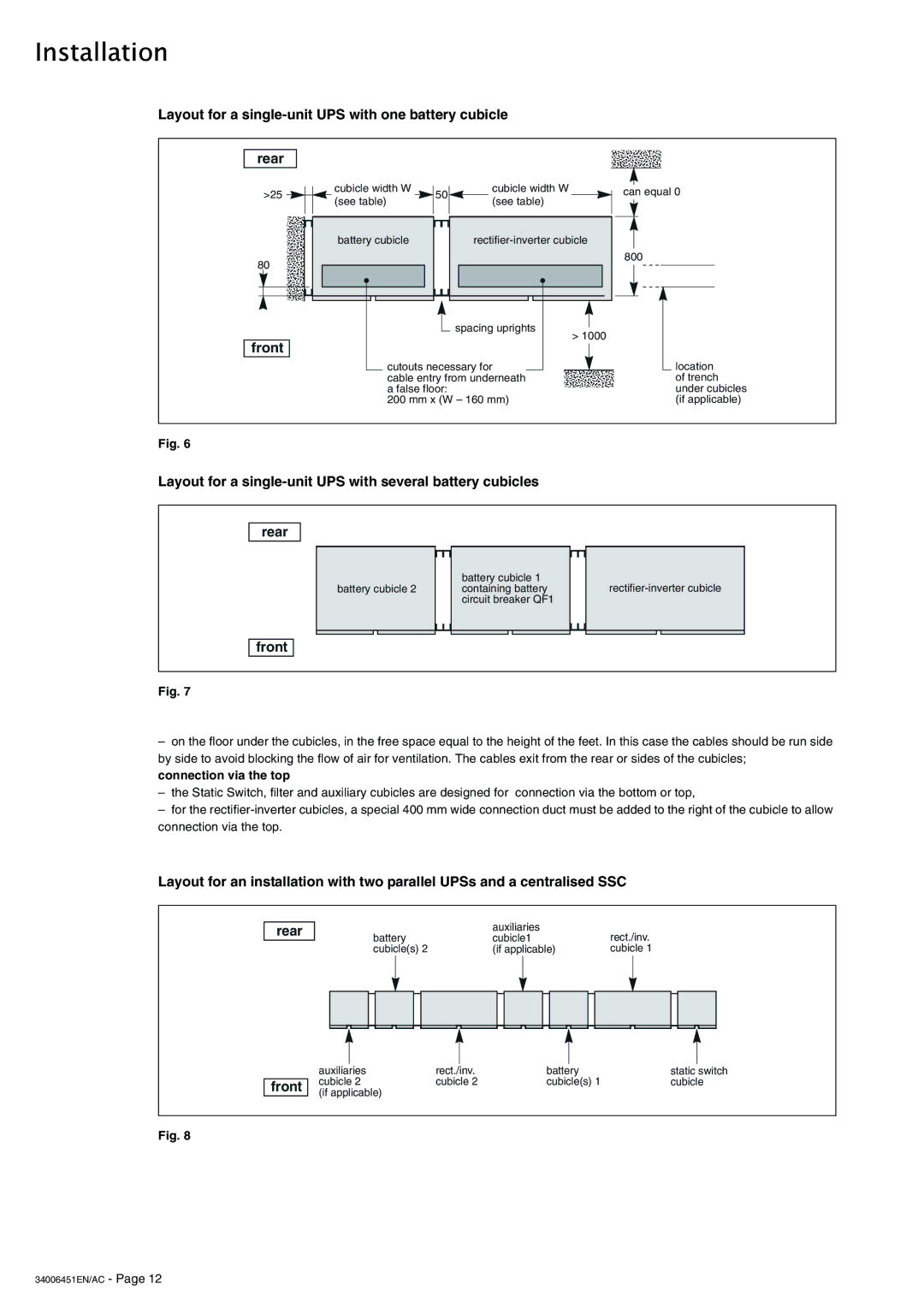
Layout for a single-unit UPS with one battery cubicle
rear
>25 | cubicle width W | 50 | cubicle width W |
|
(see table) | (see table) |
| ||
|
|
| ||
| battery cubicle |
| ||
80 |
|
|
|
|
|
|
| spacing uprights | > 1000 |
front |
|
|
| |
|
|
|
| |
| cutouts necessary for |
| ||
| cable entry from underneath |
| ||
| a false floor: |
|
| |
| 200 mm x (W – 160 mm) |
| ||
can equal 0
800
![]() location of trench under cubicles (if applicable)
location of trench under cubicles (if applicable)
Fig. 6
Layout for a
rear
battery cubicle 1
battery cubicle 2 containing batteryrectifier-inverter cubicle circuit breaker QF1
front
Fig. 7
–on the floor under the cubicles, in the free space equal to the height of the feet. In this case the cables should be run side by side to avoid blocking the flow of air for ventilation. The cables exit from the rear or sides of the cubicles; connection via the top
–the Static Switch, filter and auxiliary cubicles are designed for connection via the bottom or top,
–for the
Layout for an installation with two parallel UPSs and a centralised SSC
rear
|
|
|
| battery |
| auxiliaries |
|
|
| rect./inv. | |||||||||||||||||||||||
|
|
|
|
| cubicle1 |
|
|
| |||||||||||||||||||||||||
|
|
|
| cubicle(s) 2 |
| (if applicable) |
|
|
| cubicle 1 | |||||||||||||||||||||||
|
|
|
|
|
|
|
|
|
|
|
|
|
|
|
|
|
|
|
|
|
|
|
|
|
|
|
|
|
|
|
|
|
|
|
|
|
|
|
|
|
|
|
|
|
|
|
|
|
|
|
|
|
|
|
|
|
|
|
|
|
|
|
|
|
|
|
|
|
|
|
|
|
|
|
|
|
|
|
|
|
|
|
|
|
|
|
|
|
|
|
|
|
|
|
|
|
|
|
|
|
|
|
|
|
|
|
|
|
|
|
|
|
|
|
|
|
|
|
|
|
|
|
|
|
|
|
|
|
|
|
|
|
|
|
|
front
|
|
|
|
|
|
|
|
auxiliaries | rect./inv. | battery | static switch | ||||
cubicle 2 | cubicle 2 | cubicle(s) 1 | cubicle | ||||
(if applicable) |
|
|
|
|
|
| |
Fig. 8