Installation
Connection to battery circuit breaker QF1
Connect the cable from connector XR3 (pins 7 to 12) of the
Emergency shutdown
The UPS emergency shutdown function is generally wired to a
Important:
In the case of a complex installation with a number of units, there should only be one emergency shutdown pushbutton and this pushbutton must interrupt all the active conductors of all the units.
For the same reason, it is essential for the pushbutton to open the upstream mains 1, mains 2, and external maintenance bypass line protective circuit breakers.
Each type of unit (UPS and Static Switch Cubicle) must have an independent,
The emergency shutdown pushbutton should not be connected to the Static Switch Cubicle since the pushbutton opens the circuit breaker protecting the upstream circuit (mains 2) and the Static Switch Cubicle is therefore no longer powered (invert- ers off and mains 2 down).
2.9Connections between cubicles (modular UPSs or parallel UPSs with SSC)
On modular UPSs, interconnections are made on the APOZ (figure 17) and MISI (figures 19 to 21) boards in the UPS cubicles (see the layout of the boards in the figures in the previous section).
For parallel UPSs with a centralised SSC, interconnections are made on the APOZ boards in the UPS cubicles (figure 17) and the ACPZ boards (see the layout of the boards in the figures in the previous section) in the SSC (figure 18).
Connections between APOZ boards
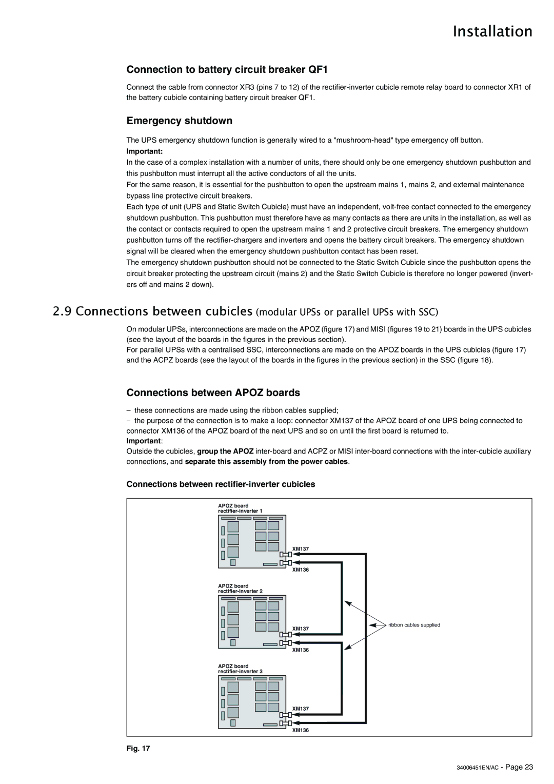
–these connections are made using the ribbon cables supplied;
–the purpose of the connection is to make a loop: connector XM137 of the APOZ board of one UPS being connected to connector XM136 of the APOZ board of the next UPS and so on until the first board is returned to.
Important:
Outside the cubicles, group the APOZ
Connections between rectifier-inverter cubicles
APOZ board
XM137
XM136
APOZ board
XM137 | ribbon cables supplied |
| |
XM136 |
|
APOZ board
XM137
XM136
Fig. 17