installation
2.7 Connection of power circuits
Before making connections, check that switches Q1, Q4S, Q3BP and Q5N are in the "open" position (toggle opposite the "O" mark).
General:
–in the case of
–for modular UPSs with an external maintenance bypass, switch Q3BP must be locked open;
–the power cables for the connections between cubicles are not supplied;
–open the doors and remove the lower terminal shields (secured by screws to the cubicle chassis) of the
–connect the cables shown in heavy lines in the wiring diagrams shown previously to the terminals specified in the figures below;
–each cubicle must be earthed;
–the routing of the power cables is shown in the figures;
–the auxiliary wiring is routed in troughs located nearby (not shown in the drawings);
–outside the cubicles, separate the auxiliary wiring from the power cables;
–all the cubicles must be interconnected for earthing, forming a mesh which is itself connected to the building structure and earthing electrode;
–the connection drawings hereafter show the cubicles with doors open and terminal shields removed.
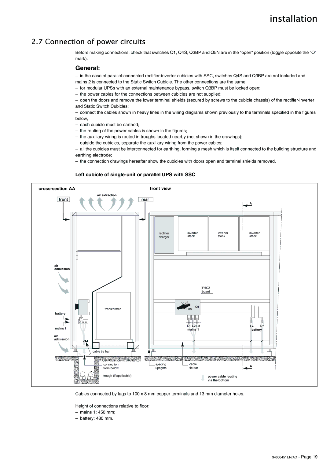
Left cubicle of single-unit or parallel UPS with SSC
| front view |
air extraction |
|
|
|
|
|
|
front | rear |
|
|
| A |
|
|
|
|
|
|
| |
| rectifier | inverter | inverter | inverter |
| |
| charger | stack |
| stack | stack |
|
air |
|
|
|
|
|
|
admission |
|
|
|
|
|
|
|
|
|
| FHCZ |
|
|
|
|
|
| board |
|
|
|
| off |
|
|
|
|
transformer |
| on | Q1 |
|
|
|
|
|
|
|
| ||
battery |
|
|
|
|
|
|
mains 1 |
| L1 L2 L3 |
| L+ | L | |
| mains 1 |
| battery | |||
|
|
| ||||
air |
|
|
|
|
|
|
admission |
|
|
|
|
|
|
cable tie bar |
|
|
|
|
|
|
connection | spacing | cable |
| A |
| |
from below | uprights | tie bar |
|
| ||
|
|
| ||||
trough (if applicable) |
|
|
| power cable routing |
|
|
|
|
|
| via the bottom |
|
|
Cables connected by lugs to 100 x 8 mm copper terminals and 13 mm diameter holes.
Height of connections relative to floor:
–mains 1: 450 mm;
–battery: 480 mm.