Installation
2.11 Connection of "Media Contacts 15" additional auxiliary circuits
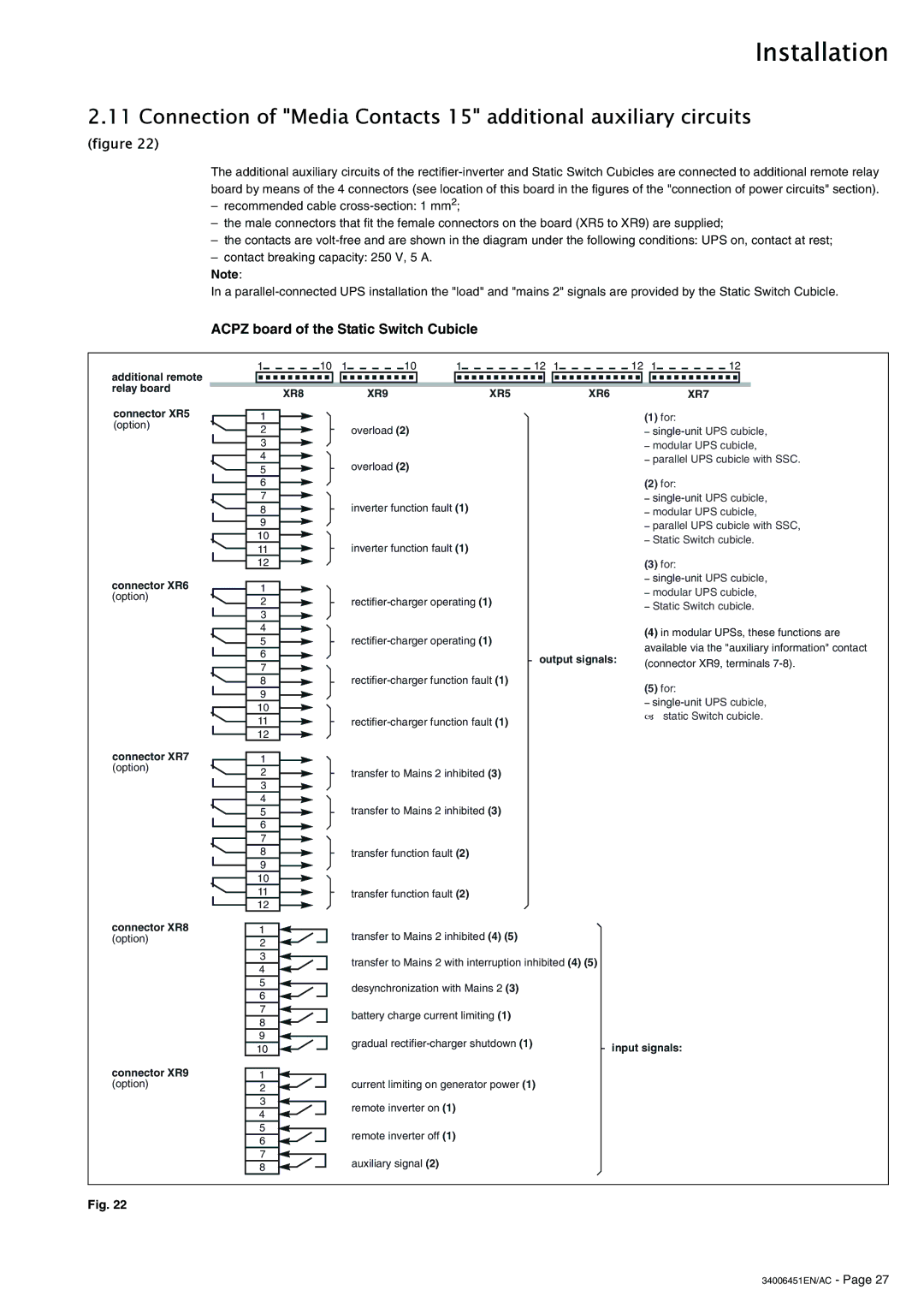
(figure 22)
The additional auxiliary circuits of the
–recommended cable
–the male connectors that fit the female connectors on the board (XR5 to XR9) are supplied;
–the contacts are
–contact breaking capacity: 250 V, 5 A.
Note:
In a
ACPZ board of the Static Switch Cubicle
additional remote relay board
connector XR5 (option)
connector XR6 (option)
connector XR7 (option)
connector XR8 (option)
connector XR9 (option)
1 |
| 10 | 1 | 10 |
| 1 | 12 | 1 | 12 | 1 | 12 |
| |||||||
|
|
|
|
|
|
|
|
|
|
|
|
|
|
|
|
|
|
|
|
|
|
|
| XR8 |
|
|
| XR9 |
| XR5 | XR6 |
|
|
| XR7 |
| |||
|
|
|
|
|
|
|
|
|
|
|
|
|
| (1) for: |
|
|
| ||
|
| 1 |
|
|
|
|
|
|
|
|
|
|
|
|
|
| |||
|
| 2 |
|
|
|
| overload (2) |
|
|
|
|
| – | ||||||
|
| 3 |
|
|
|
|
|
|
|
|
|
|
| – modular UPS cubicle, | |||||
|
| 4 |
|
|
|
| overload (2) |
|
|
|
|
| – parallel UPS cubicle with SSC. | ||||||
|
| 5 |
|
|
|
|
|
|
|
|
|
|
|
|
|
| |||
|
| 6 |
|
|
|
|
|
|
|
|
|
|
| (2) for: |
|
|
| ||
|
| 7 |
|
|
|
| inverter function fault (1) |
|
|
|
| – | |||||||
|
| 8 |
|
|
|
|
|
|
|
| – modular UPS cubicle, | ||||||||
|
| 9 |
|
|
|
|
|
|
|
|
|
|
| – parallel UPS cubicle with SSC, | |||||
|
| 10 |
|
|
|
| inverter function fault (1) |
|
|
|
| – Static Switch cubicle. | |||||||
|
| 11 |
|
|
|
|
|
|
|
| |||||||||
|
|
|
|
|
|
|
|
|
|
|
|
|
|
| |||||
|
| 12 |
|
|
|
|
|
|
|
|
|
|
| (3) for: |
|
|
| ||
|
|
|
|
|
|
|
|
|
|
|
|
|
|
| – | ||||
|
| 1 |
|
|
|
|
|
|
|
|
|
|
| – modular UPS cubicle, | |||||
|
| 2 |
|
|
|
|
|
| |||||||||||
|
|
|
|
|
|
|
| – Static Switch cubicle. | |||||||||||
|
| 3 |
|
|
|
|
|
|
|
|
|
|
| ||||||
|
|
|
|
|
|
|
|
|
|
|
|
|
|
|
|
|
| ||
|
| 4 |
|
|
|
|
|
|
|
|
|
|
| (4) in modular UPSs, these functions are | |||||
|
| 5 |
|
|
|
|
|
| |||||||||||
|
|
|
|
|
|
|
| available via the "auxiliary information" contact | |||||||||||
|
| 6 |
|
|
|
|
|
|
| output signals: | |||||||||
|
|
|
|
|
|
|
|
| (connector XR9, terminals | ||||||||||
|
| 7 |
|
|
|
|
|
|
| ||||||||||
|
|
|
|
|
|
|
|
|
|
|
|
| |||||||
|
|
|
|
|
|
|
|
|
|
|
|
| |||||||
|
| 8 |
|
|
|
|
|
| (5) for: |
|
|
| |||||||
|
| 9 |
|
|
|
|
|
|
|
|
|
|
|
|
|
| |||
|
|
|
|
|
|
|
|
|
|
|
|
| – | ||||||
|
| 10 |
|
|
|
|
|
|
|
|
|
|
| ||||||
|
|
|
|
|
|
|
|
|
|
|
|
| – static Switch cubicle. | ||||||
|
| 11 |
|
|
|
|
|
| |||||||||||
|
|
|
|
|
|
|
|
|
|
|
|
| |||||||
|
| 12 |
|
|
|
|
|
|
|
|
|
|
|
|
|
|
|
| |
|
|
|
|
|
|
|
|
|
|
|
|
|
|
|
|
|
|
| |
|
| 1 |
|
|
|
|
|
|
|
|
|
|
|
|
|
|
|
| |
|
| 2 |
|
|
|
| transfer to Mains 2 inhibited (3) |
|
|
|
|
|
|
| |||||
|
| 3 |
|
|
|
|
|
|
|
|
|
|
|
|
|
|
|
| |
|
| 4 |
|
|
|
| transfer to Mains 2 inhibited (3) |
|
|
|
|
|
|
| |||||
|
| 5 |
|
|
|
|
|
|
|
|
|
|
| ||||||
|
| 6 |
|
|
|
|
|
|
|
|
|
|
|
|
|
|
|
| |
|
| 7 |
|
|
|
|
|
|
|
|
|
|
|
|
|
|
|
| |
|
| 8 |
|
|
|
| transfer function fault (2) |
|
|
|
|
|
|
|
|
| |||
|
| 9 |
|
|
|
|
|
|
|
|
|
|
|
|
|
|
|
| |
|
| 10 |
|
|
|
|
|
|
|
|
|
|
|
|
|
|
|
| |
|
| 11 |
|
|
|
| transfer function fault (2) |
|
|
|
|
|
|
|
|
| |||
|
| 12 |
|
|
|
|
|
|
|
|
|
|
|
|
|
|
|
| |
|
|
|
|
|
|
|
|
|
|
|
|
|
|
|
|
|
|
| |
|
| 1 |
|
|
|
| transfer to Mains 2 inhibited (4) (5) |
|
|
|
|
|
|
| |||||
|
| 2 |
|
|
|
|
|
|
|
|
|
|
| ||||||
|
|
|
|
|
|
|
|
|
|
|
|
|
|
|
|
| |||
|
| 3 |
|
|
|
| transfer to Mains 2 with interruption inhibited (4) (5) |
|
|
|
|
|
| ||||||
|
| 4 |
|
|
|
|
|
|
|
|
|
| |||||||
|
|
|
|
|
|
|
|
|
|
|
|
|
|
|
|
| |||
|
| 5 |
|
|
|
| desynchronization with Mains 2 (3) |
|
|
|
|
|
|
| |||||
|
| 6 |
|
|
|
|
|
|
|
|
|
|
| ||||||
|
|
|
|
|
|
|
|
|
|
|
|
|
|
|
|
| |||
|
| 7 |
|
|
|
| battery charge current limiting (1) |
|
|
|
|
|
|
| |||||
|
| 8 |
|
|
|
|
|
|
|
|
|
|
| ||||||
|
|
|
|
|
|
|
|
|
|
|
|
|
|
|
|
| |||
|
| 9 |
|
|
|
| gradual |
| input signals: |
|
|
| |||||||
|
| 10 |
|
|
|
|
|
|
|
| |||||||||
|
|
|
|
|
|
|
|
|
|
|
|
|
| ||||||
|
|
|
|
|
|
|
|
|
|
|
|
|
|
|
|
| |||
| 1 |
|
|
|
| current limiting on generator power (1) |
|
|
|
|
|
|
| ||||||
|
| 2 |
|
|
|
|
|
|
|
|
|
|
| ||||||
|
|
|
|
|
|
|
|
|
|
|
|
|
|
|
|
| |||
|
| 3 |
|
|
|
| remote inverter on (1) |
|
|
|
|
|
|
|
|
|
| ||
|
| 4 |
|
|
|
|
|
|
|
|
|
|
|
|
|
| |||
|
|
|
|
|
|
|
|
|
|
|
|
|
|
|
|
| |||
|
| 5 |
|
|
|
| remote inverter off (1) |
|
|
|
|
|
|
|
|
|
| ||
|
| 6 |
|
|
|
|
|
|
|
|
|
|
|
|
|
| |||
|
|
|
|
|
|
|
|
|
|
|
|
|
|
|
|
| |||
|
| 7 |
|
|
|
| auxiliary signal (2) |
|
|
|
|
|
|
|
|
|
| ||
|
| 8 |
|
|
|
|
|
|
|
|
|
|
|
|
|
| |||
|
|
|
|
|
|
|
|
|
|
|
|
|
|
|
|
| |||
Fig. 22