Characteristics
The table below serves as an example for an installation comprising up to four frequency converters or four parallel UPSs with a centralised SSC.
– for installations with redundant units, take into account only the units required to supply the load power
(e.g. for an installation made up of 3
–this table has been drawn up for rated
The cable
Parameters for Mains 2 and load cables for an installation comprising frequency converters or parallel UPSs with a centralised SSC.
rated | number of | total UPS | Mains 2 or load | cable |
inverter | rated output | line current | ||
output | inverters | in kVA | in Amps | in mm² |
in kVA |
|
|
|
|
|
|
|
|
|
800 | 2 | 1600 | 2310 | Please consult us* |
| 3 | 2400 | 3465 | Please consult us* |
| 4 | 3200 | 4620 | Please consult us* |
|
|
|
|
|
900 | 2 | 1800 | 2598 | Please consult us* |
| 3 | 2700 | 3897 | Please consult us* |
| 4 | 3600 | 5196 | Please consult us* |
|
|
|
|
|
(1) cable
* NF C 15-100 authorizes a maximum of 4 cables per phase.
Installation with parallel frequency converters I
mains 1
inverter 1
mains 1
inverter 2
![]() load
load
mains 1
inverter 3
Fig. 1
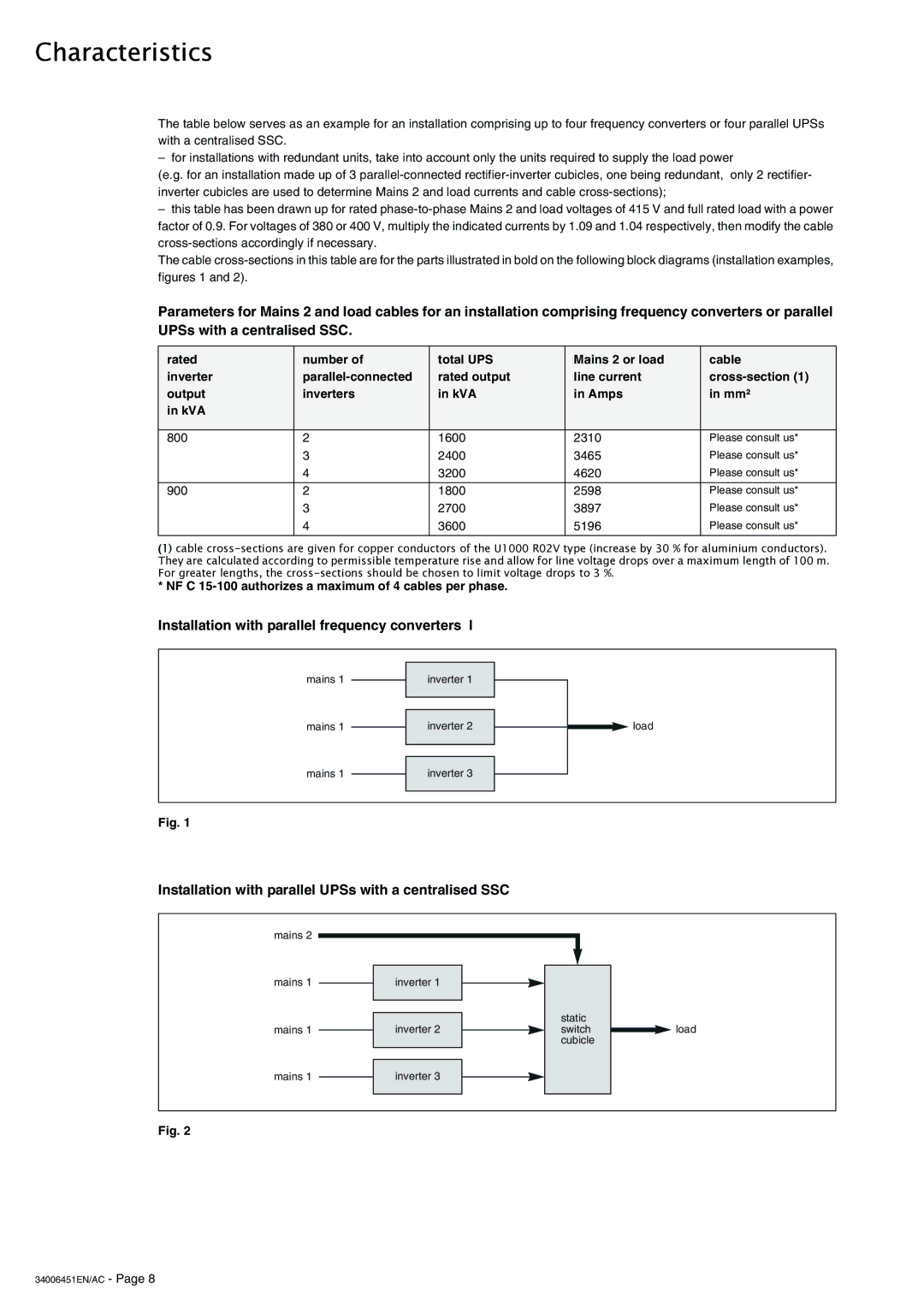
Installation with parallel UPSs with a centralised SSC
mains 2
mains 1
mains 1
inverter 1
inverter 2
static switch cubicle
![]() load
load
mains 1
inverter 3
Fig. 2