Characteristics
1.5Electrical parameters for determining cable cross-sections
–this table has been drawn up for rated
–the current values and cable
–the battery current values and cable
–the current values and cable sections for Mains 2 and load are given for full rated load with a power factor of 0.9.
For frequency converters, the parameters concerning Mains 2 are not applicable.
The load parameters common to all the converters are given in the table below.
For a parallel UPS, the parameters for Mains 2 and load are also provided in the table below.
For a modular UPS, the parameters for Mains 2 and load are also provided in the table below.
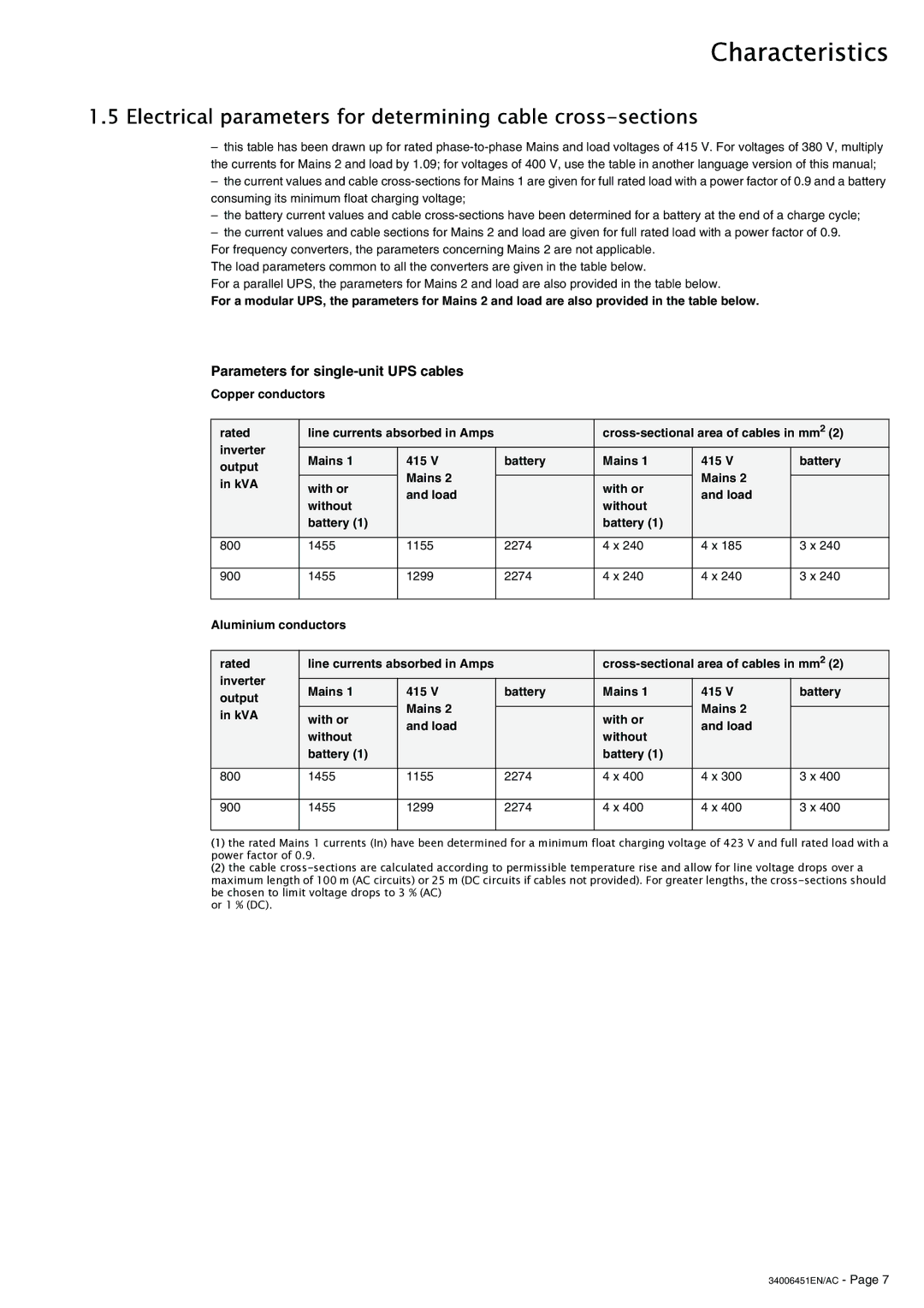
Parameters for single-unit UPS cables
Copper conductors
rated | line currents absorbed in Amps |
| |||||
inverter | Mains 1 | 415 V | battery | Mains 1 | 415 V | battery | |
output | |||||||
| Mains 2 |
|
| Mains 2 |
| ||
in kVA | with or |
| with or |
| |||
and load |
| and load |
| ||||
|
|
| |||||
| without |
| without |
| |||
|
|
|
|
| |||
| battery (1) |
|
| battery (1) |
|
| |
|
|
|
|
|
|
| |
800 | 1455 | 1155 | 2274 | 4 x 240 | 4 x 185 | 3 x 240 | |
900
1455
1299
2274
4 x 240
4 x 240
3 x 240
Aluminium conductors
rated | line currents absorbed in Amps |
| |||||
inverter |
|
|
|
|
|
| |
Mains 1 | 415 V | battery | Mains 1 | 415 V | battery | ||
output | |||||||
| Mains 2 |
|
| Mains 2 |
| ||
in kVA | with or |
| with or |
| |||
and load |
| and load |
| ||||
|
|
| |||||
| without |
| without |
| |||
|
|
|
|
| |||
| battery (1) |
|
| battery (1) |
|
| |
|
|
|
|
|
|
| |
800 | 1455 | 1155 | 2274 | 4 x 400 | 4 x 300 | 3 x 400 | |
900
1455
1299
2274
4 x 400
4 x 400
3 x 400
(1)the rated Mains 1 currents (In) have been determined for a minimum float charging voltage of 423 V and full rated load with a power factor of 0.9.
(2)the cable
or 1 % (DC).