Installation
Internal connections between cubicles
–removal of inverter leg no.6 is recommended prior to bolting
–first remove the two fuses and the two cables connected to the leg;
–then pull the leg out;
–bolt
–refit inverter leg no 6;
–intended only for transportation, the front gussets do not need to be refitted;
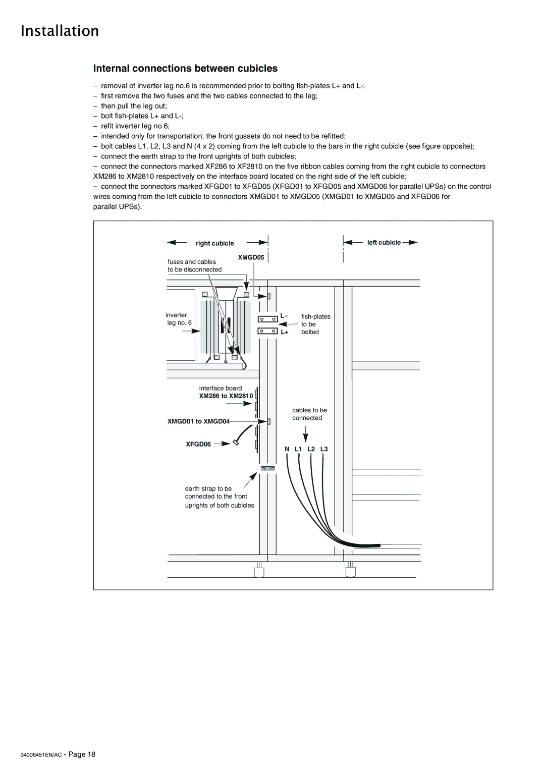
–bolt cables L1, L2, L3 and N (4 x 2) coming from the left cubicle to the bars in the right cubicle (see figure opposite);
–connect the earth strap to the front uprights of both cubicles;
–connect the connectors marked XF286 to XF2810 on the five ribbon cables coming from the right cubicle to connectors XM286 to XM2810 respectively on the interface board located on the right side of the left cubicle;
–connect the connectors marked XFGD01 to XFGD05 (XFGD01 to XFGD05 and XMGD06 for parallel UPSs) on the control wires coming from the left cubicle to connectors XMGD01 to XMGD05 (XMGD01 to XMGD05 and XFGD06 for
parallel UPSs).
right cubicle | left cubicle |
fuses and cables | XMGD05 |
| |
to be disconnected |
|
inverter | L | |
leg no. 6 |
| to be |
| L+ | bolted |
interface board |
|
|
XM286 to XM2810 |
|
|
|
| cables to be |
XMGD01 to XMGD04 |
| connected |
|
| |
XFGD06 | N | L1 L2 L3 |
| ||
earth strap to be |
|
|
connected to the front |
|
|
uprights of both cubicles |
|
|