Installation
2.5 Power circuit wiring diagrams
The
(see the table in the previous chapter for the required
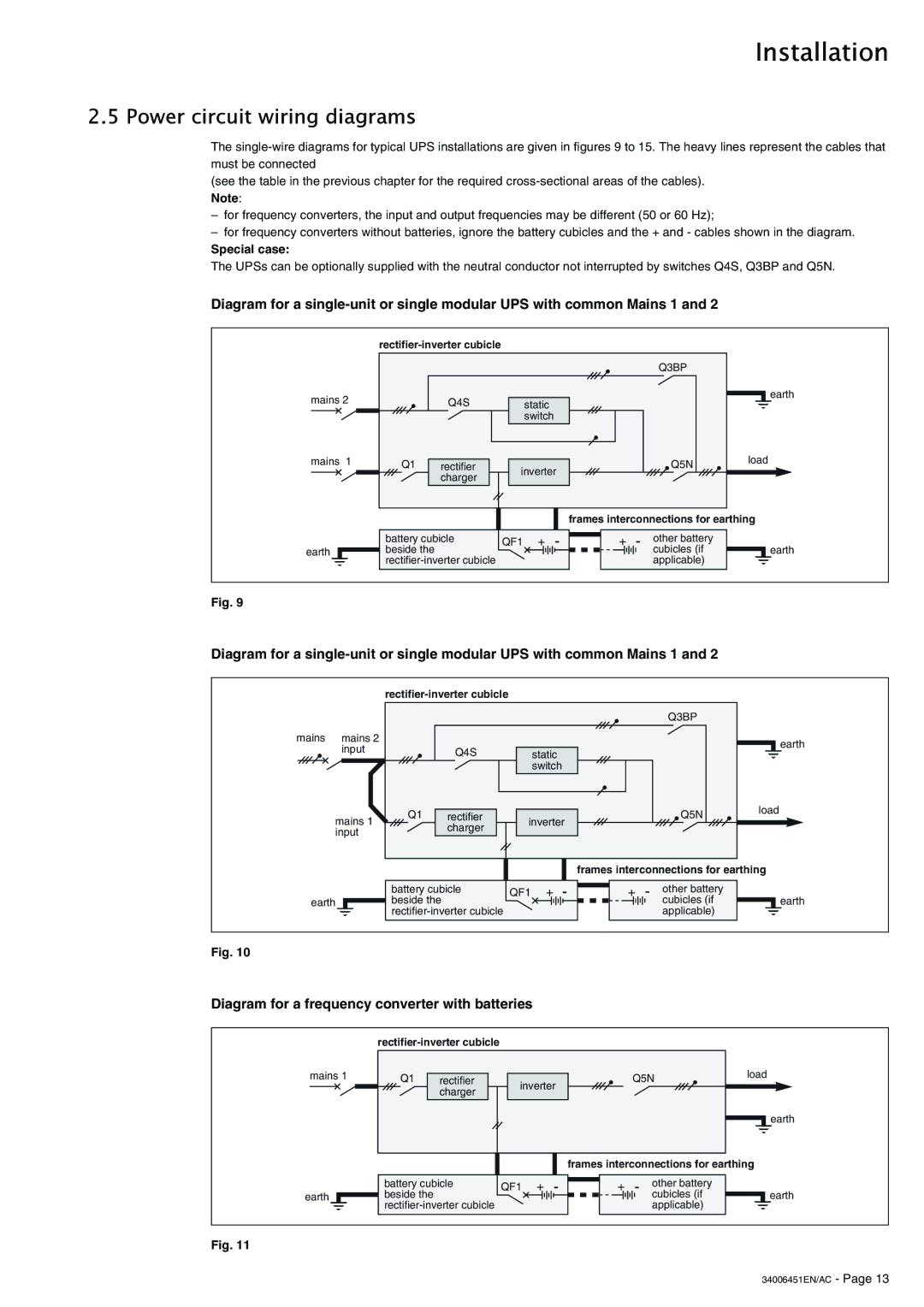
–for frequency converters, the input and output frequencies may be different (50 or 60 Hz);
–for frequency converters without batteries, ignore the battery cubicles and the + and - cables shown in the diagram.
Special case:
The UPSs can be optionally supplied with the neutral conductor not interrupted by switches Q4S, Q3BP and Q5N.
Diagram for a
mains 2
mains 1
earth
|
|
| Q3BP |
|
| Q4S | static |
| earth |
|
|
| ||
|
| switch |
|
|
Q1 | rectifier | inverter | Q5N | load |
| ||||
| charger |
|
| |
|
|
|
|
frames interconnections for earthing
battery cubicle | QF1 + | - |
| + | - | other battery |
|
|
|
|
|
|
|
|
| ||||||
beside the |
|
|
|
|
| cubicles (if |
|
| earth | |
|
|
|
|
| applicable) |
|
|
|
| |
|
|
|
|
|
|
|
|
| ||
|
|
|
|
|
|
|
|
|
|
|
Fig. 9
Diagram for a
|
|
|
|
| Q3BP |
|
mains | mains 2 |
|
|
|
| earth |
| input |
| Q4S | static |
| |
|
|
|
| |||
|
|
|
| switch |
|
|
| mains 1 | Q1 | rectifier | inverter | Q5N | load |
|
| |||||
|
| charger |
|
| ||
| input |
|
|
|
| |
|
|
|
|
|
|
earth
battery cubicle | QF1 + | |
beside the |
|
|
|
| |
|
| |
-
frames interconnections for earthing
+ - | other battery | ||
|
|
| cubicles (if |
|
|
| applicable) |
|
|
|
|
earth
Fig. 10
Diagram for a frequency converter with batteries
mains 1
earth
|
|
|
|
|
|
|
| ||
Q1 | rectifier | inverter |
| Q5N | load |
| |||
|
|
| |||||||
| charger |
|
|
|
|
| |||
|
|
|
|
|
|
|
|
| |
|
|
|
|
|
|
|
|
| earth |
|
|
|
|
| frames interconnections for earthing |
| |||
battery cubicle | QF1 | + | - | + | - | other battery |
|
| |
beside the |
|
|
|
|
|
| cubicles (if |
| earth |
|
|
|
|
| applicable) |
|
| ||
Fig. 11