Installation
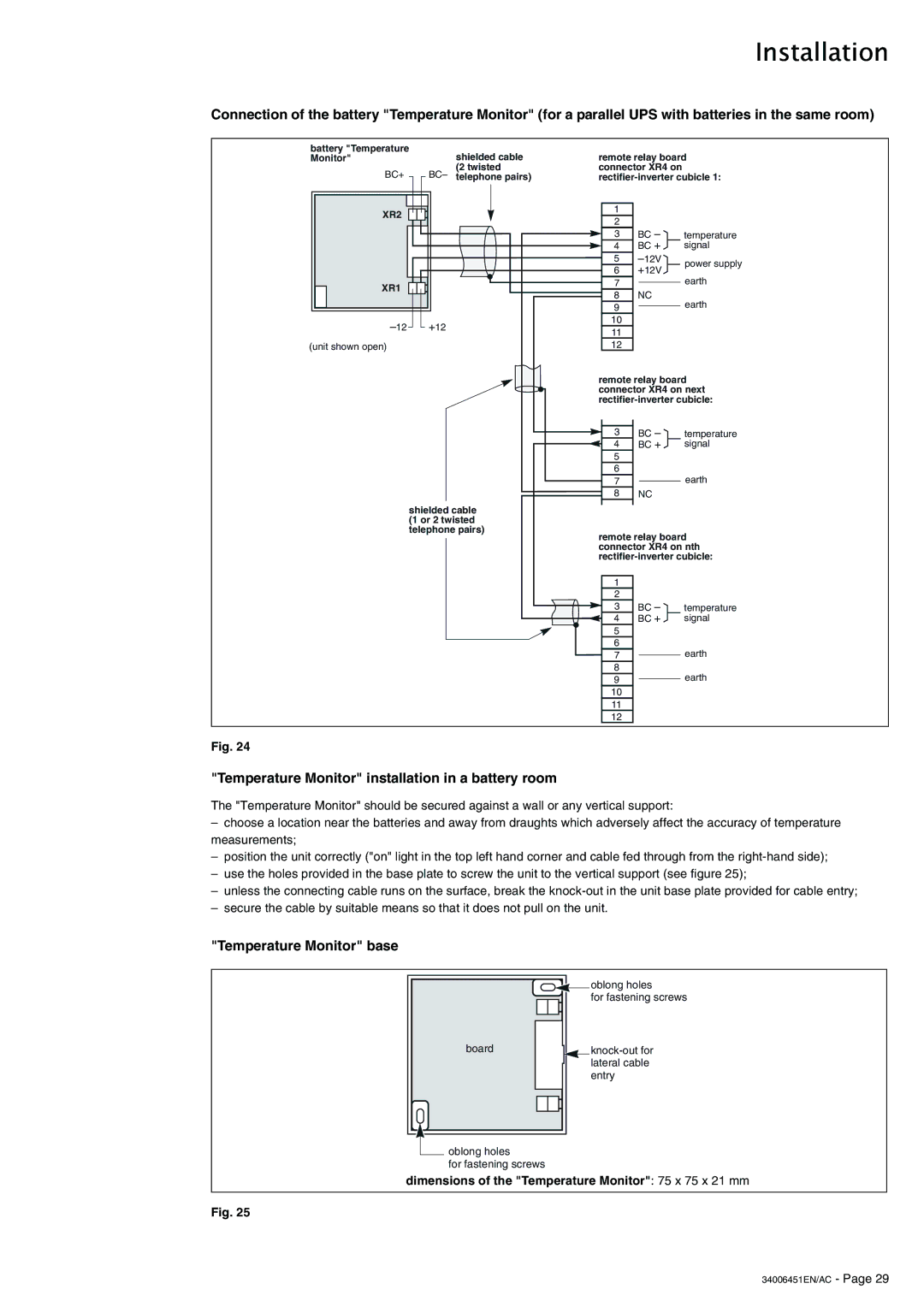
Connection of the battery "Temperature Monitor" (for a parallel UPS with batteries in the same room)
battery "Temperature Monitor"
BC+
XR2
XR1
(unit shown open)
shielded cable (2 twisted
BC– telephone pairs)
+12
remote relay board connector XR4 on
1 |
|
| |
2 |
|
| |
3 | BC – | temperature | |
4 | BC + | signal | |
5 | power supply | ||
6 | +12V | ||
|
7earth
8NC
9earth
10
11
12
remote relay board connector XR4 on next
shielded cable (1 or 2 twisted telephone pairs)
| BC – |
|
3 | temperature | |
4 | BC + | signal |
5 |
|
|
6 |
|
|
7![]()
![]() earth
earth
8 NC
remote relay board connector XR4 on nth
1 |
|
|
2 |
|
|
3 | BC – | temperature |
4 | BC + | signal |
5 |
|
|
6 |
|
|
7earth
8
9earth
10
11
12
Fig. 24
"Temperature Monitor" installation in a battery room
The "Temperature Monitor" should be secured against a wall or any vertical support:
–choose a location near the batteries and away from draughts which adversely affect the accuracy of temperature measurements;
–position the unit correctly ("on" light in the top left hand corner and cable fed through from the
–use the holes provided in the base plate to screw the unit to the vertical support (see figure 25);
–unless the connecting cable runs on the surface, break the
–secure the cable by suitable means so that it does not pull on the unit.
"Temperature Monitor" base
board
![]() oblong holes
oblong holes
for fastening screws
oblong holes
for fastening screws
dimensions of the "Temperature Monitor": 75 x 75 x 21 mm
Fig. 25