Installation
Connections between MISI boards (modular UPSs)
See figures 19 to 21.
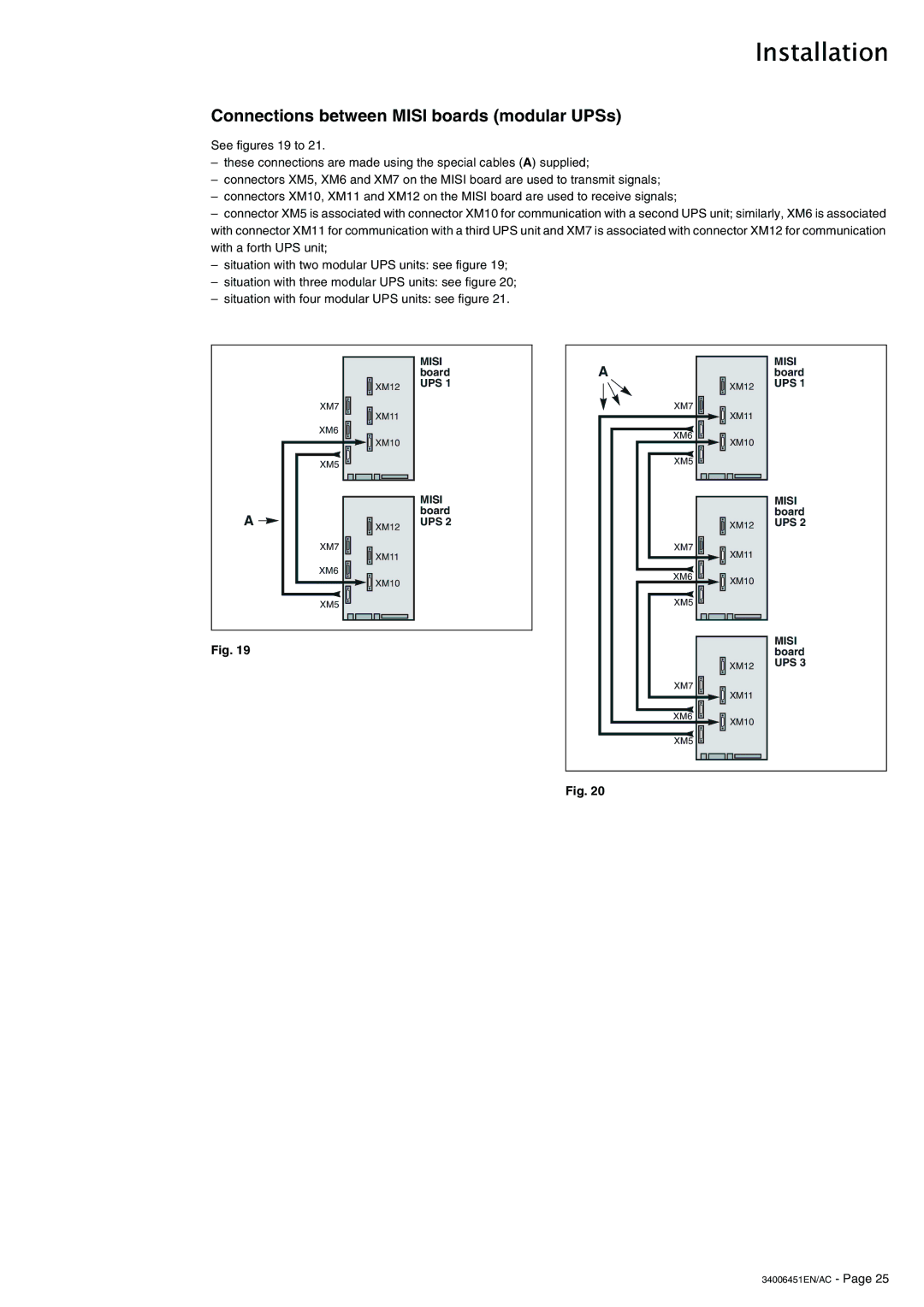
–these connections are made using the special cables (A) supplied;
–connectors XM5, XM6 and XM7 on the MISI board are used to transmit signals;
–connectors XM10, XM11 and XM12 on the MISI board are used to receive signals;
–connector XM5 is associated with connector XM10 for communication with a second UPS unit; similarly, XM6 is associated with connector XM11 for communication with a third UPS unit and XM7 is associated with connector XM12 for communication with a forth UPS unit;
–situation with two modular UPS units: see figure 19;
–situation with three modular UPS units: see figure 20;
–situation with four modular UPS units: see figure 21.
|
| MISI |
|
| board |
| XM12 | UPS 1 |
|
| |
| XM7 |
|
| XM11 |
|
| XM6 |
|
| XM10 |
|
| XM5 |
|
|
| MISI |
A |
| board |
XM12 | UPS 2 | |
|
| |
| XM7 |
|
| XM11 |
|
| XM6 |
|
| XM10 |
|
| XM5 |
|
Fig. 19
A |
| MISI |
| board | |
| XM12 | UPS 1 |
XM7 | XM11 |
|
|
| |
XM6 | XM10 |
|
|
| |
XM5 |
|
|
|
| MISI |
|
| board |
| XM12 | UPS 2 |
XM7 | XM11 |
|
|
| |
XM6 | XM10 |
|
|
| |
XM5 |
|
|
|
| MISI |
|
| board |
| XM12 | UPS 3 |
XM7 | XM11 |
|
|
| |
XM6 | XM10 |
|
|
| |
XM5 |
|
|
Fig. 20