Characteristics
The table below serves as an example for an installation with up to four modular UPSs with an external maintenance bypass.
– for installations with redundant units, take into account only the units required to supply the load power
(e.g. for an installation made up of 3
–this table has been drawn up for rated
The cable
–important. In an installation with an external maintenance bypass, the power cables between each UPS and the upstream protection devices must be the same length. The same holds for the power cables between each UPS cubicle and the external maintenance bypass.
rated | number of | total UPS | mains 2 or load | cable |
inverter | rated output | line current | ||
output | inverters | in kVA | in Amps | in mm² |
in kVA |
|
|
|
|
|
|
|
|
|
800 | 2 | 1600 | 2310 | Please consult us* |
| 3 | 2400 | 3465 | Please consult us* |
| 4 | 3200 | 4620 | Please consult us* |
|
|
|
|
|
900 | 2 | 1800 | 2598 | Please consult us* |
| 3 | 2700 | 3897 | Please consult us* |
| 4 | 3600 | 5196 | Please consult us* |
|
|
|
|
|
(1) cable
* NF C 15-100 authorizes a maximum of 4 cables per phase.
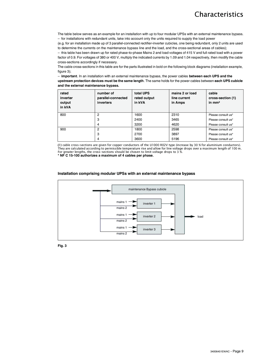
Installation comprising modular UPSs with an external maintenance bypass
maintenance Bypass cubicle
mains 1 | inverter 1 |
| |
mains 2 |
|
mains 1 mains 2
inverter 2
load
mains 1 mains 2
inverter 3
Fig. 3