Characteristics
1.4 Electrical parameters for selecting protective devices
The parameters given in the table below can be used to determine the required rating of the source side protective circuit breaker on Mains 1 of a
Important:
It is essential to choose the type of circuit breaker according to its breaking capacity and the prospective
Note:
For Mains 1 power supply voltages of 380, 400 and 415 V, the Mains 1 current is the same because it is a function of the DC voltage.
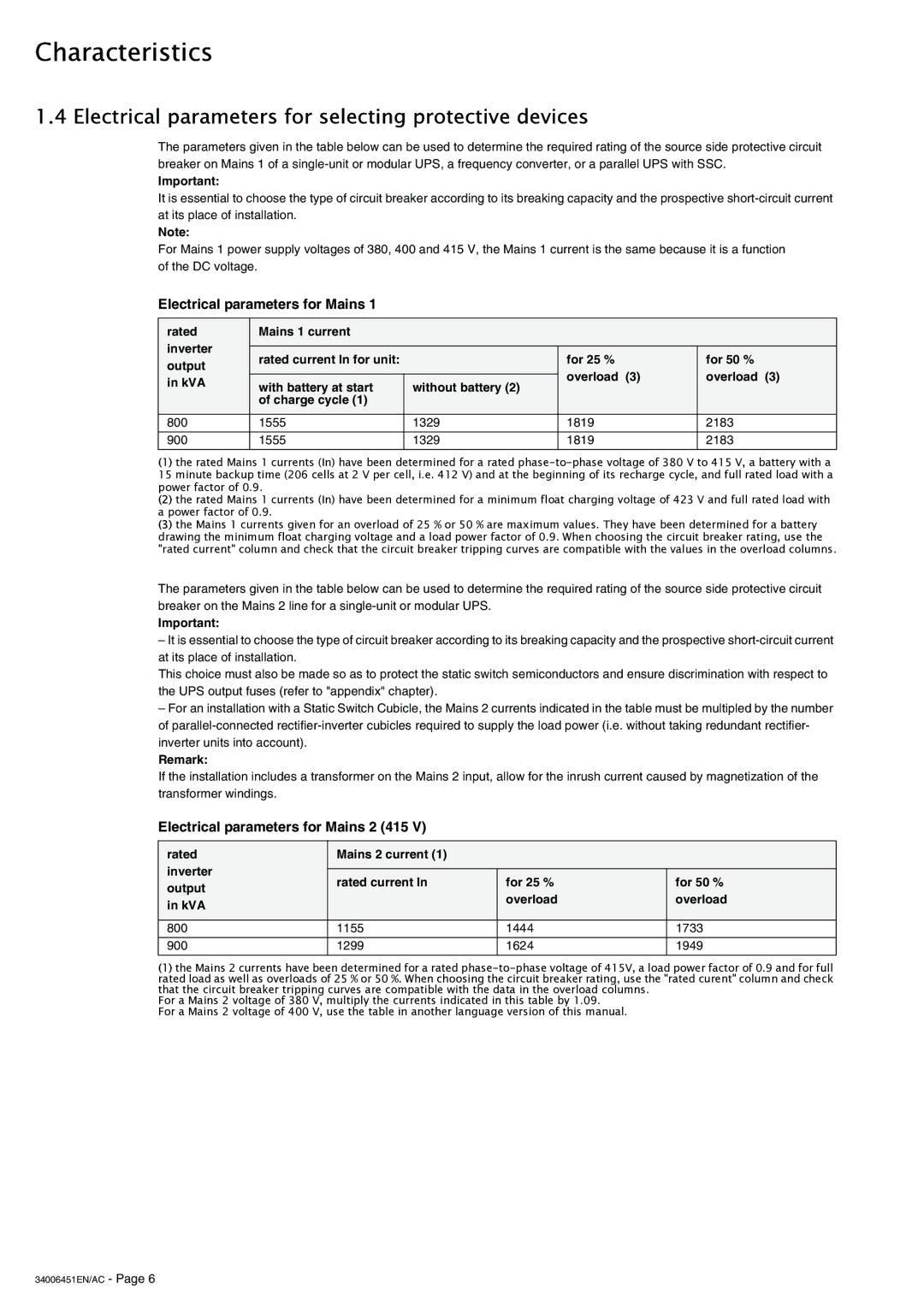
Electrical parameters for Mains 1
rated | Mains 1 current |
|
|
| |
inverter |
|
|
|
| |
rated current In for unit: |
| for 25 % | for 50 % | ||
output |
| ||||
|
| overload (3) | overload (3) | ||
in kVA | with battery at start | without battery (2) | |||
|
| ||||
|
|
| |||
| of charge cycle (1) |
|
|
| |
|
|
|
|
| |
800 | 1555 | 1329 | 1819 | 2183 | |
|
|
|
|
| |
900 | 1555 | 1329 | 1819 | 2183 | |
|
|
|
|
|
(1)the rated Mains 1 currents (In) have been determined for a rated
15 minute backup time (206 cells at 2 V per cell, i.e. 412 V) and at the beginning of its recharge cycle, and full rated load with a power factor of 0.9.
(2)the rated Mains 1 currents (In) have been determined for a minimum float charging voltage of 423 V and full rated load with a power factor of 0.9.
(3)the Mains 1 currents given for an overload of 25 % or 50 % are maximum values. They have been determined for a battery drawing the minimum float charging voltage and a load power factor of 0.9. When choosing the circuit breaker rating, use the "rated current" column and check that the circuit breaker tripping curves are compatible with the values in the overload columns.
The parameters given in the table below can be used to determine the required rating of the source side protective circuit breaker on the Mains 2 line for a
Important:
–It is essential to choose the type of circuit breaker according to its breaking capacity and the prospective
This choice must also be made so as to protect the static switch semiconductors and ensure discrimination with respect to the UPS output fuses (refer to "appendix" chapter).
–For an installation with a Static Switch Cubicle, the Mains 2 currents indicated in the table must be multipled by the number of
Remark:
If the installation includes a transformer on the Mains 2 input, allow for the inrush current caused by magnetization of the transformer windings.
Electrical parameters for Mains 2 (415 V)
rated | Mains 2 current (1) |
|
| |
inverter |
|
|
| |
rated current In | for 25 % | for 50 % | ||
output | ||||
| overload | overload | ||
in kVA |
| |||
|
|
| ||
|
|
|
| |
800 | 1155 | 1444 | 1733 | |
|
|
|
| |
900 | 1299 | 1624 | 1949 | |
|
|
|
|
(1)the Mains 2 currents have been determined for a rated
For a Mains 2 voltage of 380 V, multiply the currents indicated in this table by 1.09.
For a Mains 2 voltage of 400 V, use the table in another language version of this manual.