Installation
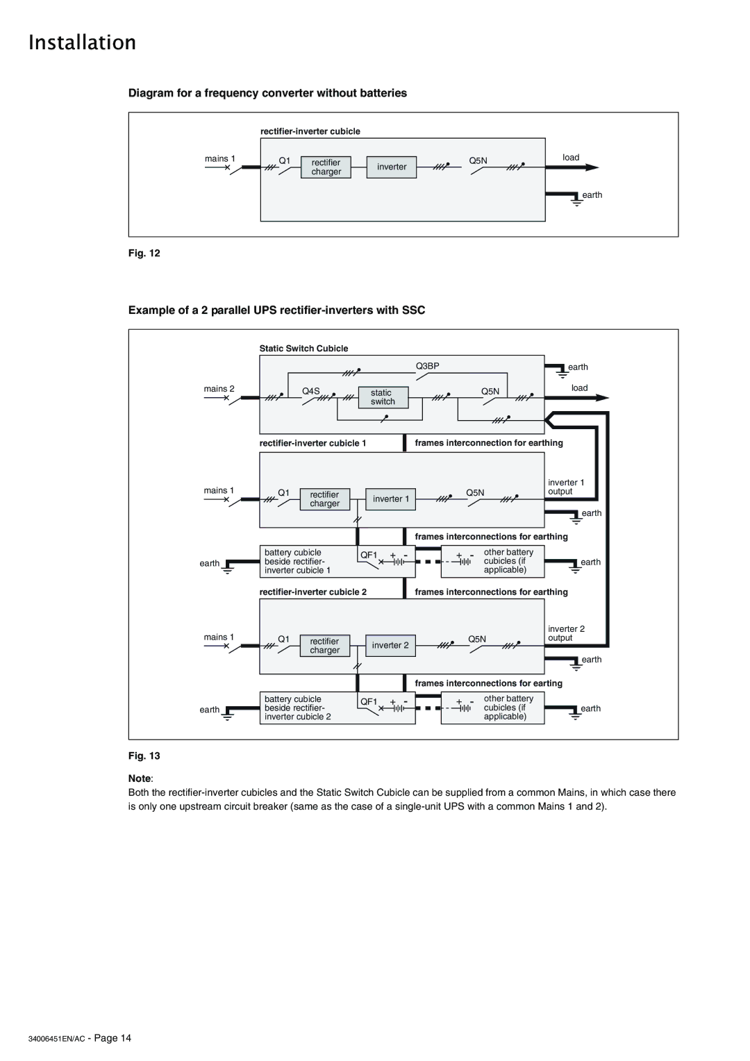
Diagram for a frequency converter without batteries
| ||||
mains 1 |
| Q1 |
|
|
| rectifier |
| ||
|
|
| charger |
|
inverter
Q5Nload
earth
Fig. 12
Example of a 2 parallel UPS rectifier-inverters with SSC
mains 2
mains 1
earth
mains 1
earth
Static Switch Cubicle
| Q3BP |
| earth |
Q4S | static | Q5N | load |
| |||
| switch |
|
|
frames interconnection for earthing |
|
|
|
|
|
|
|
| inverter 1 |
Q1 | rectifier | inverter 1 |
| Q5N | output | |||
| charger |
|
|
|
| |||
|
|
|
|
|
|
| earth | |
|
|
|
|
|
|
|
| |
|
|
|
|
| frames interconnections for earthing | |||
battery cubicle | QF1 | + | - | + | - | other battery |
| |
beside rectifier- | cubicles (if | earth | ||||||
inverter cubicle 1 |
|
|
|
|
| applicable) |
| |
|
| frames interconnections for earthing | ||||||
|
|
|
|
|
|
|
| inverter 2 |
Q1 | rectifier | inverter 2 |
| Q5N | output | |||
| charger |
|
|
|
| |||
|
|
|
|
|
|
| earth | |
|
|
|
|
|
|
|
| |
|
|
|
|
| frames interconnections for earting | |||
battery cubicle | QF1 | + | - | + | - | other battery |
| |
beside rectifier- | cubicles (if | earth | ||||||
inverter cubicle 2 |
|
|
|
|
| applicable) |
| |
Fig. 13
Note:
Both the