Installation
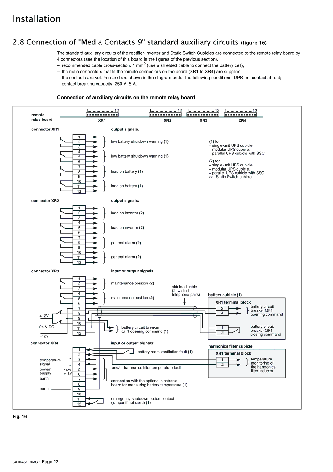
2.8 Connection of "Media Contacts 9" standard auxiliary circuits (figure 16)
The standard auxiliary circuits of the
–recommended cable
–the male connectors that fit the female connectors on the board (XR1 to XR4) are supplied;
–the contacts are
–contact breaking capacity: 250 V, 5 A.
Connection of auxiliary circuits on the remote relay board
1 | 12 | 1 | 12 | 1 | 12 | 1 | 12 |
| ||||||||
remote |
|
|
|
|
|
|
|
|
|
|
|
|
| |||
relay board |
|
|
|
|
|
|
|
|
|
|
|
|
|
|
|
|
|
|
|
| XR1 |
| XR2 |
| XR3 |
| XR4 | ||||||
connector XR1 | output signals: |
|
|
|
|
|
|
|
|
|
| |||||
|
|
|
|
|
|
|
|
|
|
|
|
|
|
|
| |
|
| 1 |
| low battery shutdown warning (1) |
| (1) for: |
|
|
|
| ||||||
|
| 2 |
|
|
|
|
|
| ||||||||
|
|
| 3 |
|
|
|
|
|
|
| – | |||||
|
|
|
|
|
|
|
| – modular UPS cubicle, | ||||||||
|
|
| 4 |
|
|
|
|
|
|
| ||||||
|
| low battery shutdown warning (1) |
| – parallel UPS cubicle with SSC. | ||||||||||||
|
|
| 5 |
|
| (2) for: |
|
|
|
| ||||||
|
|
| 6 |
|
|
|
|
|
|
|
|
|
|
| ||
|
|
|
|
|
|
|
|
|
|
| – | |||||
|
|
| 7 |
|
|
|
|
|
|
| ||||||
|
|
|
|
|
|
|
| – modular UPS cubicle, | ||||||||
|
|
| 8 |
| load on battery (1) |
|
|
|
| |||||||
|
|
|
|
|
| – parallel UPS cubicle with SSC, | ||||||||||
|
|
| 9 |
|
|
|
|
|
|
| – Static Switch cubicle. | |||||
|
|
| 10 |
| load on battery (1) |
|
|
|
|
|
|
|
|
|
| |
|
|
| 11 |
|
|
|
|
|
|
|
|
|
|
| ||
|
|
| 12 |
|
|
|
|
|
|
|
|
|
|
|
|
|
connector XR2
connector XR3
1
2
3
4
5
6
7
8
9
10
11
12
1
output signals:
load on inverter (2)
load on inverter (2)
general alarm (2)
general alarm (2)
input or output signals:
+12V
2
3
4
5
6
7
8
9
maintenance position (2)
maintenance position (2)
shielded cable (2 twisted telephone pairs)
battery cubicle (1)
XR1 terminal block
3battery circuit breaker QF1
4 | opening command |
24 V DC
connector XR4
temperature signal
power
supply +12V earth
earth
10
11
12
1
2
3
4
5
6
7
8
9
10
11
12
battery circuit breaker QF1 opening command (1)
input or output signals:
battery room ventilation fault (1)
and/or harmonics filter temperature fault
connection with the optional electronic board for measuring battery temperature (1)
emergency shutdown button contact (jumper if not used) (1)
| battery circuit | |
1 | ||
| breaker QF1 | |
2 | ||
closing command | ||
|
harmonics filter cubicle
XR1 terminal block
1 | temperature | |
2 | monitoring of | |
the harmonics | ||
|
filter inductor
Fig. 16