Contents
Apollo 120 /150
Copyright Notice
Unpacking
Apollo III main system
Important Safety Precautions
Page
Table of Contents
Hardware Installation and Upgrade
System Motherboard & I/O Board
103
139
Touchscreen
145
Introduction
Apollo 120/150
General Information
What Covers in this Manual
Apollo 120/150
Specifications
System
Ethernet
Audio Function
Peripheral & Storate Devices
Mechanical & Environmental
Dimensions
Apollo
Apollo 150 Dimension
Apollo 120/150
Using the System
Identifying the System
Front View
Side Views
Left side of the panel PC appears as below
3. I/O Outlets
System Setup for the First-time Use
Installation Procedures
Running the Bios Setup
Operating System and Driver Installation
Apollo 120/150
Versatile Standing & Mounting Options
Versatile Stand
Standing Upright
2 to 900 Free Standing
Fixed Standing
Apollo òy¼Ò²Õ
Cable Management
Wall Mounting and Mobile Applications
Apollo 120 Vesa Holes
Apollo 150 Vesa Holes
Panel Mounting
Kiosk Integration
10 Apollo Kiosk Illustration
O Connection
Parallel Port
COM Ports x
Apollo 120/150
10 Base-T Ethernet RJ-45
VGA Interface
Pin Description
Nd Display Graphic Support Mode
When System Memory Clock = 66MHz
Single Display Mode
When LCD is selected as secondary display at mirror mode
Multiple Display Output Mode
When System Memory Clock = 100MHz
120 56, 60, 72, 75 1024*768
640*480 60, 72, 75, 85 60, 70 120, 160 60,70 800*600
When System Memory Clock = 133MHz
Single Display Mode
640*480 60, 72, 75, 85
Multiple Display Output Mode
PS/2 Keyboard Interface
PS/2 Mouse Interface
External FDD DB-15
Trko
+5V/12V DC-Out
VR Brightness Control
DIO Digital Input & Output
Read SD0, SD1 Write SD4, SD5
Digital I/O Programming
Example
USB Ports
15. AC/DC Inlet/Power Switch
Audio Interface Line-in, MIC-in, SPK-out
IR Keyboard Sensor optional
Hardware Installation and Upgrade
Apollo 120/150
Recognizing the System Major Parts
Apollo 120 ¥DÅé²Õ«~
Apollo 150 Exploded Diagram
Installing the CPU
Installing the Sdram Memory Module
Motherboard Assembly
Touch Controller Assembly
HDD Module Assembly
HDD Installation
Touchscreen or Front Bezel Assembly
Apollo W/O Touch
Apollo 120 Front Bezel Assembly
LCD Module Assembly
8APOLLO 120 LCD Module Assembly
Through the rectangle opening at the rear side
Apollo 120/150
CD-ROM/DVD-ROM/FDD Module Assembly
Internal CD-ROM/FDD Assembly
10CD-ROM/FDDMODULE Assembly
External FDD Connection
Power Module Assembly
Appendix
11 Apollo AC Power Module
Expansion Outlets & Riser Card Assembly
Back Panel Assembly
12 Apollo Back Module Assembly
Stand Module Assembly
13 Apollo Pedestal Assembly
14 Apollo Stand to Main System Assembly
System Motherboard & I/O Board
Apollo III Motherboard
General Information
Standard I/O
Specifications
Main Chipset SiS630ST
Ethernet
Hardware Monitor
Display
Audio Function
Expansion Bus PCI/ISA x
Locating Jumpers & Connectors
Jumpers & Jumper Setting
Jumper Description
JP10
JP5 JP6 JP7 JP8 JP9
Connectors & Pin Assignment
Pin # Signal
CIR
Pin # Signal
GND Shfclk FLM
Backlight ADJ
IDE1/IDE2 Primary/Secondary HDD
Scsi 1 Parallel Port/Serial Port/DIO Port
GND Hsync
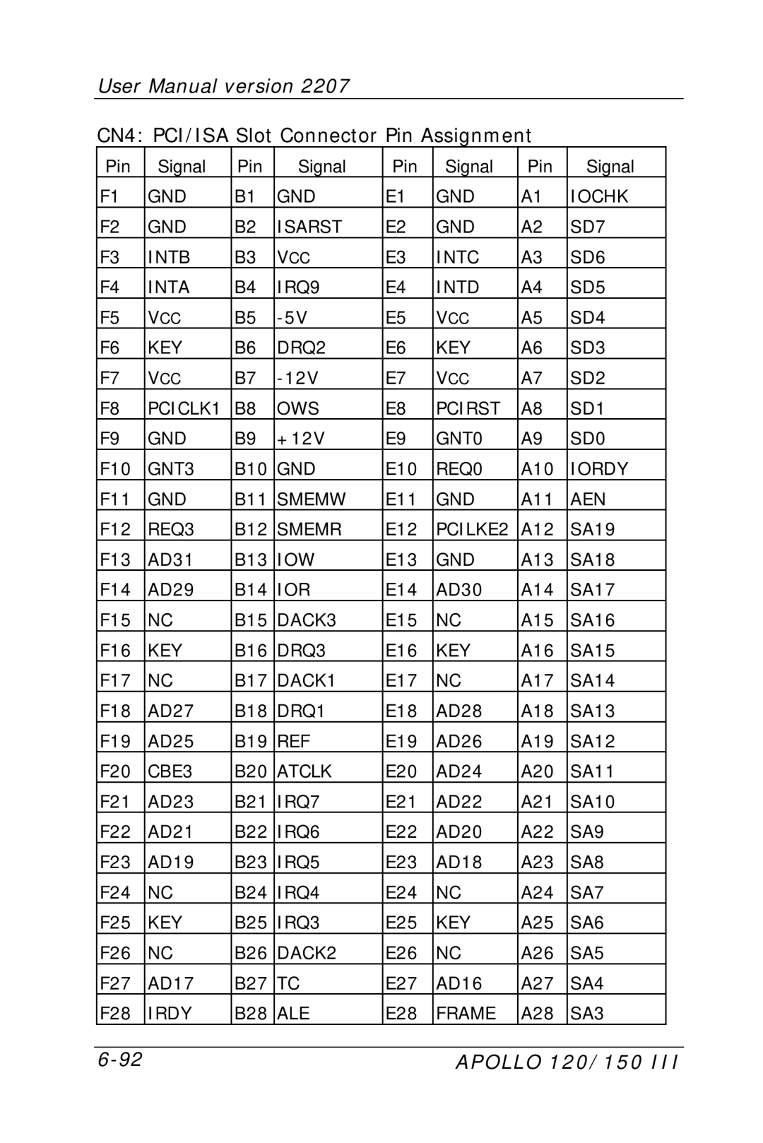
5.14. CN4 PCI/ISA Expansion Slot
CN4 PCI/ISA Slot Connector Pin Assignment
To continue …
Apollo III I/O Board
JP1
KB1
Kbdata GND SB5V Kbclk
STRB# AFD# Data ERROR# INIT# SLINT# GND ACK# Busy Slct
USB1 USB2
100
Apollo 120/150 101
102
Apollo 120/150 103
Award Bios
Control Key Definition
Apollo 120/150 105
Getting Help
Award Bios Setup
Award Bios Setup Main Menu
Main Menu
Apollo 120/150 107
Standard Cmos Features
EGA/VGA
Apollo 120/150 109
110
Advanced Bios Features
Apollo 120/150 111
Choice Enabled & Disabled
CPU L2 Cache ECC Checking
Apollo 120/150 113
Typematic Delay Msec
OS Select for Dram 64MB
Advanced Chipset Features
Apollo 120/150 115
RAS to CAS Delay
Sdram RAS Active Time
Sdram RAS Precharge Time
Early CKE Delay Adjust
VCM REF to ACT/REF Delay
VCM Acct to ACT/REF Delay
LD-OFFDRAM RD/WR Cycles
Sdwclk Control CS#/CKE
SDRAM/VCM CAS Latency
Sdrclk Control
Sdwclk Control MA/SRAS
Apollo 120/150 119
120
Integrated Peripherals
Apollo 120/150 121
Internal PCI / IDE
IDE Primary Master/Slave PIO
SIS-7018 AC97 Audio
SIS-900 10/100M Ethernet
Apollo 120/150 123
ECP Mode USE DMA
IDE HDD Block Mode
Power Management Setup
Apollo 120/150 125
126
Apollo 120/150 127
IRQ 3-7,9-15, NMI
7.PnP/PCI Configuration
Apollo 120/150 129
IRQ3/4/5/7/9/10/11/12/14/15 Assigned to
PC Health Status
Apollo 120/150 131
Frequency Voltage Control
Auto Detect DIMM/PCI CLK
CPU HOST/DRAM/PCI Clock
Apollo 120/150 133
Load Fail-Safe Defaults
Load Optimized Defaults
Apollo 120/150 135
User Password
Enter Password
Save and Exit Setup
Apollo 120/150 137
Exit Without Saving
Quit without Saving Y/N ? N
Software & Drivers Installation
Apollo 120/150 139
Ethernet Drivers
PC 610 AGP XGA
Apollo 120/150 141
Audio Setup
² DOS
Driver Installation
Apollo 120/150 143
144
Touchscreen
Apollo 120/150 145
MicroTouch Touch Driver Installation
Two types of MicroTouch touchscreens
TouchWare-the MicroTouch Software
Apollo 120/150 147
TouchWare Uninstall
Online Help
Installing TouchWare
Apollo 120/150 149
150
Uninstalling TouchWare
Apollo 120/150 151
Calibrate the MicroTouch Touchscreen
Getting More Information
Apollo 120/150 153
Elo Touchscreen Driver Installation
System Requirements
About Elo Software
Software Included
Apollo 120/150 155
Installation
Command Line Flags
Apollo 120/150 157
158
Why Calibration is Necessary
Apollo 120/150 159
When Recalibration is Necessary
MonitorMouse for Windows
All Elo Software
Installing MonitorMouse for Win
Apollo 120/150 161
162
Removing the Mouse Pointer
Apollo 120/150 163
MonitorMouse for Windows 95 Uninstall Procedure
MONMOUSE.CPL
Installing MonitorMouse for Win NT
Apollo 120/150 165
Instruction for Windows NT Auto Boot
Apollo 120/150 167
LCD Specification
LCD for Apollo
Apollo 120 High Luminanace LCD
Apollo 120/150 169
LCD for Apollo
DiskOnChip Installation
Apollo 120/150 171
Address range Hex Device
Wake-On-LAN
Download the Wake up packet
Apollo 120/150 173
Wake up Packet
Apollo 120/150 175
First MB Memory Map
Address range Hex Device
Power Supply
Apollo 120/150 177
² Safety standards
² Dimension unit mm

