User Manual version 2207
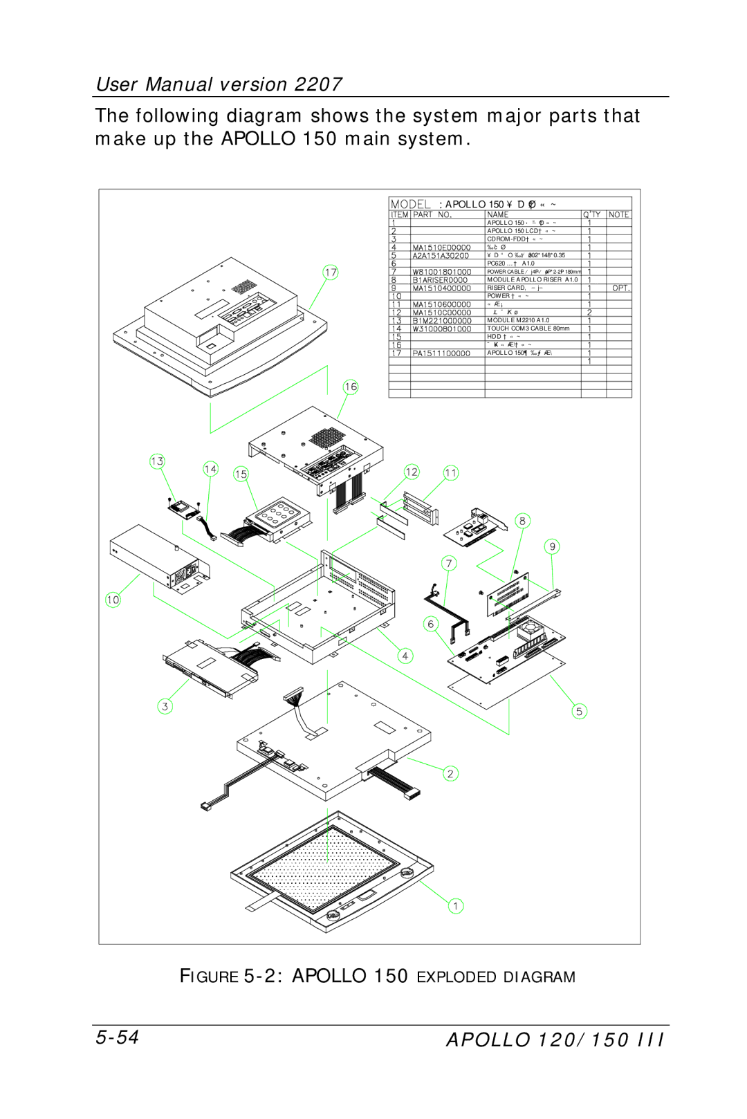
The following diagram shows the system major parts that make up the APOLLO 150 main system.
APOLLO 150 ¥DÅé²Õ«~ |
APOLLO 150 |
APOLLO 150 LCD²Õ«~ |
|
½cÅé |
¥D¾÷ªOµ´½t¤ù302*148*0.35 |
PC620 ¼Ò²ÕA1.0 |
POWER CABLE |
MODULE APOLLO RISER A1.0 |
RISER CARD¸É±j±ì |
POWER ²Õ«~ |
«áµ¡ |
µL¤ÕÅK¤ù |
MODULE M2210 A1.0 |
TOUCH COM3 CABLE 80mm |
HDD ²Õ«~ |
ÅK¥ó«á»\²Õ«~ |
APOLLO 150¶ì½¦«á»\ |
FIGURE |
APOLLO 120/150 III |
